background image

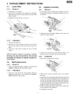
3.5. Power Cord / On-Off Switch

Replacement

3.5.1. Removal

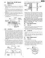
 1. Remove the dust cover and switch cover to expose the

electrical connections of the power cord, on-off switch and
wire cord.

 2. Pull the power cord into the dust compartment in order to

remove the strain relief (for power cord replacement) by
prying or cutting, remove the wire connections, and wire tie,
if present.

 3. Remove the on-off switch (for on-off switch replacement) by

depressing the retaining tabs while pushing up and out of
the dust compartment at the same time.

 4. Pull the power cord out of the dust compartment (for power

cord replacement).

3.5.2. Installation

 1. Insert the new power cord (power cord replacement only)

into the dust compartment as far as necessary in order to
place a new cord retainer in proper location on power cord.
The proper location is approximately one and one eighth
inches/thirty millimeters (1 1/8”/30 mm) of new power cord
outer jacket extending past the cord retainer and washer.
The washer goes between the cord retainer and the dust
compartment. Attach wires with wire connectors according
to the wiring diagram in the front of this manual. ONLY USE
A NEW CORD RETAINER, DO NOT REUSE A CORD
RETAINER.

 2. For switch replacement only, insert the new ON/OFF switch

with the numbers 1,2,3, facing toward you, into the dust
compartment until secured by the retaining tabs. Use a wire
tie in the location illustrated taking care not to overtighten it.
Tuck the wire connectors back into the dust compartment
as illustrated in the close-up view.

 3. Ensure that the insulator packing is installed correctly.

 4. Replace the switch cover, the two (2) switch cover screws,

and the dust cover. Care should be taken not to pinch wires
and make sure that the switch cover goes on easily and
stays flat. If there is resistance to the switch cover lying flat
and in place, stop, remove the cover and make sure that no
wires are being pinched. DO NOT USE A POWER
SCREWDRIVER TO SECURE THE COVER.

NOTE: For general servicing, it is necessary to eliminate
pinching of any wire during reassembly. After servicing
any electrical component or electrical enclosure, the unit
should

be

reassembled

and

checked

for

dielectric

breakdown or current leakage.

3.6. Hose Replacement

3.6.1. Removal

 1. Remove the end of the hose from the tool holder and then

remove the hose adapter by unscrewing it.

 2. Remove the other end of the hose by depressing the two

tabs which secure it to the back of the dust compartment.

3.6.2. Installation

 1. Install the new hose. Insert the hose adapter into the tool

holder.

 2. Install the new hose to the back of the dust container by

pressing it into place until the tabs are securely locked into
the dust compartment.

3.7. Motor Replacement

3.7.1. Removal

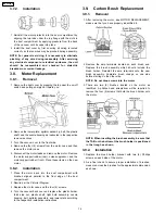
 1. Remove the dust cover and dust bag.

 2. Remove the motor protector by pushing in, one at a time,

on the tabs that secure it to the dust compartment. Push the
motor protector out the back of the dust compartment.

 3. Once the motor protector has been removed it can be

disassembled for replacement of parts.

13

MC-V5504-00

Содержание MC-V5504-00

Страница 1: ...F MATSUSHITA ELECTRIC CORPORATION OF AMERICA All rights reserved Unauthorized copying and distribution is a violation of law MC V5504 00 Vacuum Cleaner Specifications are subject to change without notice for further improvement Order Number MAC0404002C1 E4 ...

Страница 2: ... 2 4 Packing Material 10 3 REPLACEMENT INSTRUCTIONS 11 3 1 Lower Plate 11 3 2 Belt Replacement 11 3 3 Agitator Assembly 11 3 4 Nozzle Housing Replacement 12 3 5 Power Cord On Off Switch Replacement 13 3 6 Hose Replacement 13 3 7 Motor Replacement 13 3 8 Motor Replacement 14 3 9 Carbon Brush Replacement 14 3 10 Motor Fan 15 CONTENTS Page Page 2 MC V5504 00 ...

Страница 3: ...1 WIRING DIAGRAM AND DRAWING 1 1 Wiring Diagram 3 MC V5504 00 ...

Страница 4: ...ervicing it is necessary to eliminate pinching of any wire during reassembly After servicing any electrical component or electrical enclosure the unit should be reassembled and checked for dielectric breakdown or current leakage 4 MC V5504 00 ...

Страница 5: ...2 EXPLODED VIEW AND PARTS LIST 2 1 Body 2 1 1 Exploded View 5 MC V5504 00 ...

Страница 6: ... F70E Cover Suction Inlet 1 20 AXTN4 16BFY Screw Suction Inlet 2 Shipped 10 per package 21 AC09FAECZV07 Motor Case 1 22 AMC02L V00 Packing Rear Cover 1 23 AC19FJPZV06 Packinig Motor Case 1 24 AXTN4 20BFY Screw Motor Case 4 Shipped 10 per package 25 AC92FTEZ0U Motor Fan 1 26 AC38HAPNZ0U Cover Cap 1 27 AXYN4 E10FFY Screw Ground 1 28 AC99GAMMZ000 Noise Suppressor 1 29 AMC03F V00 Motor Support Rear 1 ...

Страница 7: ...embly Ref No Part No Part Name Description Quantity Remarks 1 AMC53F AV00U Fan Case 1 2 AMC33F AC00U Nut 1 3 AMC62F AV00U Washer 1 4 AC98FRFZ00 Fan 1 5 AMC60F AV00U Spacer 1 6 AC27FRFZ00 Brush Assembly 1 set 7 AC02DV3Z0U Bracket 2 8 AC40DV3Z0U Screw 4 7 MC V5504 00 ...

Страница 8: ...2 3 Nozzle Housing 2 3 1 Exploded View 8 MC V5504 00 ...

Страница 9: ...per package 10 AC28SJPZ00 Belt 1 11 AC91AARFZ00 Lower Plate Assembly 1 12 AC27AARFZ00 Lower Plate 1 13 AC07ZADFZ00 Warning Label 1 14 AMC11S 2V0W Belt Cover Rear 1 15 AC70NYUZ00 Stop Latch Spring 2 16 AMC68N V30K Latch 2 17 AMC51A 2V0 Pedal Shaft 1 18 AMC74S Z100G Spacer 1 19 AC74AAAEZ00 Packing Lower Plate Front 1 20 AXTN4 28BFY Screw Spacer 1 Shipped 10 per package 21 AMC68A V30 Screw Nozzle 2 S...

Страница 10: ...aterial 2 4 1 Exploded View 2 4 2 Parts List Ref No Part No Part Name Description Quantity Remarks 1 AC61ZCCAZOOO Packaging Assembly 1 Includes 1 and items a g 2 ACO1ZCMYZOOO Operating Instructions 1 10 MC V5504 00 ...

Страница 11: ...t and follow the installation instructions in the AGITATOR ASSEMBLY REMOVAL INSTALLTION section 3 3 Agitator Assembly 3 3 1 Removal 1 The brushes are not replaceable separately When the brushes need replacing the agitator assembly will have to be replaced 2 Carefully lift up on the agitator assembly until it clear both sides of the nozzle housing 3 Remove the belt from the motor shaft by sliding i...

Страница 12: ...handle release assembly 3 4 2 Installation 1 Install the nozzle packing if not already in place window and handle release assembly in the new nozzle housing 2 Fit the nozzle around the motor shaft side first and rotate it into place on the dust container as illustrated 3 Slide the plastic shaft through the nozzle housing and into the dust container Make sure that the slot on the bottom of the plas...

Страница 13: ...tighten it Tuck the wire connectors back into the dust compartment as illustrated in the close up view 3 Ensure that the insulator packing is installed correctly 4 Replace the switch cover the two 2 switch cover screws and the dust cover Care should be taken not to pinch wires and make sure that the switch cover goes on easily and stays flat If there is resistance to the switch cover lying flat an...

Страница 14: ... 1 Place the motor back into the dust compartment with brushes aligned parallel to the front edge of the dust compartment 2 Rewire per the Pictorial Diagram 3 Replace the motor case and the four 4 screws 4 Turn the vacuum back over and replace the plastic holder thick side out plastic shaft light bulb assembly nozzle housing belt agitator assembly and lower plate according to the respective instal...

Страница 15: ...rench on the nut place the 1 8 inch Allen wrench into the end of the motor shaft and loosen the nut while holding the Allen wrench still The nut will have to be turned clockwise as it is a left hand thread After removing the nut remove the fan There is a spacer left on the motor that is not required to be removed If spacer is removed reassemble per exploded view 3 10 2 Installation 1 Place the new...

Отзывы: