3.7.2. Installation
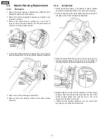
1. Reinstall the motor protector into the dust compartment by
aligning the two tabs under the top flange with the slots in
the dust compartment by applying pressure from the back
of the vacuum until it snaps into place.
2. Install the dust cover by first ensuring all wiring is routed
correctly so that no wires may be pinched during assembly.
NOTE: For general servicing, it is necessary to eliminate
pinching of any wire during reassembly. After servicing
any electrical component or electrical enclosure, the unit
should
be
reassembled
and
checked
for
dielectric
breakdown or current leakage.
3.8. Motor Replacement
3.8.1. Removal
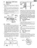
1. Remove the dust cover by grasping the top near the on-off
switch and pulling sharply out toward you.
2. Remove the lower plate, agitator assembly, belt, the plastic
shaft, and the nozzle housing as instructed in the respective
removal sections.
3. Turn the vacuum over to the front side.
4. Remove the four (4) screws from the motor case and then
remove the motor case.
5. Disconnect the motor leads and remove the motor. Remove
the motor support rubber (rear), noise suppressor, and the
motor support rubber (front). Place these items on the new
motor.
3.8.2. Installation
1. Place the motor back into the dust compartment with
brushes aligned parallel to the front edge of the dust
compartment.
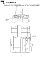
2. Rewire per the Pictorial Diagram.
3. Replace the motor case and the four (4) screws.
4. Turn the vacuum back over and replace the plastic holder,
thick side out, plastic shaft, light bulb assembly, nozzle
housing, belt, agitator assembly, and lower plate according
to the respective installation instructions.
3.9. Carbon Brush Replacement
3.9.1. Removal
1. After removing the motor, see MOTOR REPLACEMENT,
make sure that you have properly indentified it.
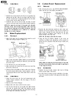
2. Remove the amp terminals located on each brush end.
Replace the brush assembly which should include the
brush holder. Reinstall the amp terminals onto the new
brush assembly. Complete brush change on one side
before starting on the other side.
NOTE: Do not drop screws into the motor.
3. There are two (2) brushes located on the motor as
identified. A phillips head screwdriver will be required to
remove the four (4) screws that hold the brush holder onto
the motor.
NOTE: When inserting the brush assembly, be sure that
the TAB on the bottom of the brush holder is positioned
in the trough as shown.
3.9.2. Installation
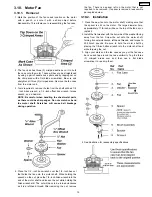
1. Replace the brush holder bracket with two (2) Phillips
screws on each side of the motor.
2. As a final check to assure proper installation of brushes,
measure across the brushes for the approximate dimension
as shown.
14
MC-V5504-00


