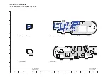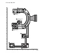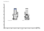
S-13
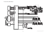
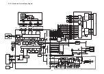
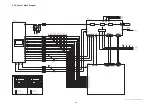
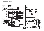
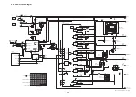
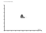
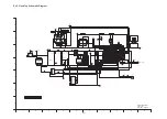
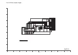
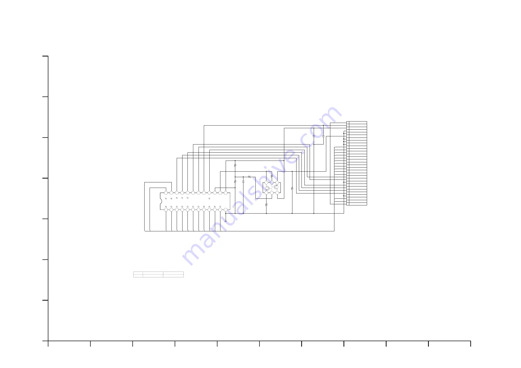
S4.5. CCD Flex Schematic Diagram
10
9
8
7
6
5
4
3
2
1
F
E
D
C
B
A
G
DMC-LZ3/LZ4/LZ5
CCD Flex
Schematic Diagram
+%
4
4
-
4
4
4
4
72.
3
%
(,#
(*%#
%
%
(6
8
8
84
84
8.
8.
8#
8#
8$
8$
8
8
8#
8#
8$
8$
85
85
8
8
8
8
8.
8.
84
84
4
8.
8.
8#
8#
84
84
85
85
8
8
8
8
8#
8#
8
8
8$
8$
8$
8$
8
8
26
*.
*.
57$59
57$
57$
8.
8.
84
84
*
*
*
*
4)
)0&
)0&
81
8&&
%%&A)0&
%%&A)0&
%%&A)0&
%%&A)0&
%%&A)0&
$57$
)7#4&
%%&176
)7#4&
8*
8.
%10A%*-
%10A%*-
61/#+0A%0
8CTKCVKQP%CVGIQT[
+%
.<
.<
/02/8
/02/8
Содержание Lumix DMC-LZ3PP
Страница 11: ...11 4 Specifications...
Страница 12: ...12 5 Location of Controls and Components...
Страница 19: ...19 8 Disassembly and Assembly Instructions 8 1 Disassembly Flow Chart 8 2 PCB Location...
Страница 21: ...21 Fig D2 8 3 2 Removal of the LCD Unit Fig D3 8 3 3 Removal of the SD Cover Fig D4...
Страница 22: ...22 8 3 4 Removal of the Top Case Unit Fig D5 8 3 5 Removal of the Flash Top PCB and AF Assist PCB Fig D6...
Страница 23: ...23 Fig D7 8 3 6 Removal of the Main PCB Fig D8 Fig D9 8 3 7 Removal of the Battery Case Unit Fig D10...
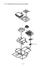
Страница 54: ...S7 3 Packing Parts and Accessories Section S 25 205 209 212 211 210 200 202 203 204 Not supplied 206 207...

