85
4-4 I/O Rating/Circuit
4-4-1 Input rating and input circuit
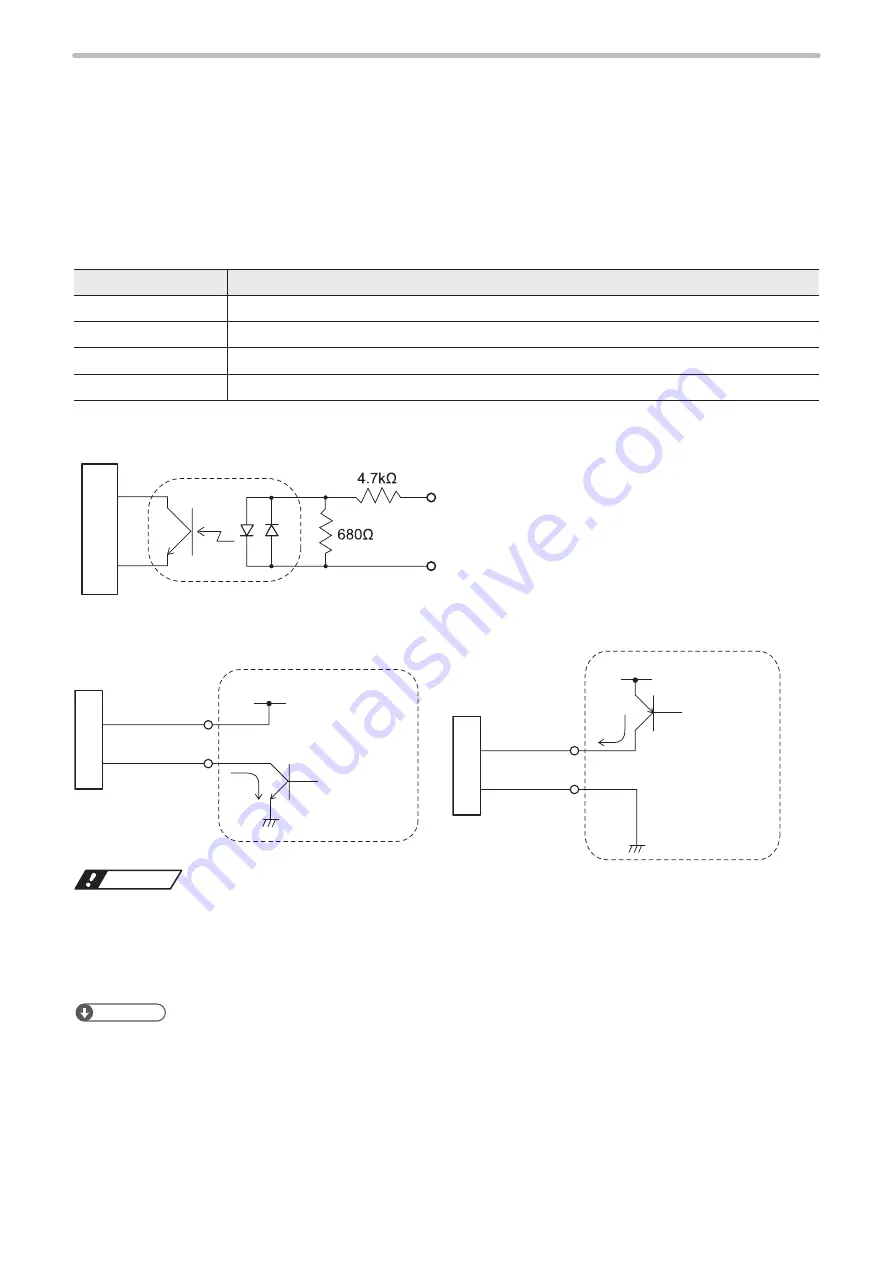
This section shows the input rating and the input circuit for the I/O terminal block input and the I/O connector input. Note
that the input rating and circuit of INTERLOCK terminals (X16, X17, X18, X19) are different from those shown here. Refer to
“4-4-3 Interlock terminal rating and I/O circuit” (P.87).
Input rating
Item
I/O terminal block input, I/O connector input
Input form
Bidirectional photo coupler insulation input
Input ON voltage
Difference of voltages between input and input common: 19V or more
Input OFF voltage
Difference of voltages between input and input common: No more than 3V or open
Rated input voltage
+24V DC+/-10%
Input circuit
In
te
rn
al
c
irc
uit
INPUT
Input common
(IN COM.)
NPN sample
PNP sample
IN
PU
T
IN
PU
T
Input common
(IN COM.)
Input
common
(IN COM.)
External power
supply
(+24V DC)
External power
supply
(+24V DC)
NPN open
collector output
PNP open
collector output
Each input
Each input
ワㄐㄕㄊㄆ
• This product supports both the NPN transistor output and the PNP transistor output. However, the wiring from I/O
terminal block and the I/O connector respectively cannot be used as NPN/PNP mixed. Operate the product after
selecting either NPN or PNP.
• Do not short-circuit 24V OUT (X1, Y3) and 0V OUT (Y1, X3). Also, do not short-circuit IN COM. 1 (X2) and OUT COM.2
(Y2, X12). Starting the laser marker with these terminals short-circuited will cause the laser marker to malfunction.
ンㄆㄇㄆㄓㄆㄏㄆ
• Respective inputs are bidirectional photo-coupler inputs. The regulation for input ON is based on the ON status of photo-
coupler.
• IN COM. 1, OUT COM. 1 of the I/O terminal block and IN COM. 2, OUT COM. 2 of the I/O connector are independent.
If you use the I/O connector terminal, connect input common/output common of the I/O terminal block and the I/O
connector to power supply respectively.
• DC 2-wire sensor cannot be connected to any input.
ME-LPGS-SM-8
Содержание LP-GS Series
Страница 17: ...1 Product Overview ME LPGS SM 8 ...
Страница 32: ...2 Laser Marker Installation ME LPGS SM 8 ...
Страница 48: ...3 Operation Method ME LPGS SM 8 ...
Страница 68: ...4 External Control Using I O ME LPGS SM 8 ...
Страница 107: ...5 External Control by Communication Commands ME LPGS SM 8 ...
Страница 116: ...6 Link Control with External Devices ME LPGS SM 8 ...
Страница 141: ...7 Maintenance ME LPGS SM 8 ...
Страница 161: ...161 MEMO ME LPGS SM 8 ...
Страница 162: ...Troubleshooting ME LPGS SM 8 ...
Страница 186: ...Index ME LPGS SM 8 ...
Страница 188: ...188 Unit power cable 26 USB 30 45 V Vibration resistance 33 W Warning 177 Z Z axis adjustment module 154 ME LPGS SM 8 ...
Страница 189: ......
Страница 190: ... Panasonic Industrial Devices SUNX Co Ltd 2014 2019 April 2019 ...


