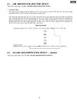
4.5. LINE AMPLIFIER AND SIDE TONE CIRCUIT
Change from original page 162 (6.8.5. LINE AMPLIFIER AND SIDE TONE CIRCUIT)
1. Circuit Operation
The reception signal output from the line transformer T101 is input to pin (6) of IC101 via C126 and R131, and then the signal
is amplified at pin (7) of IC101 and sent to the reception system at 5dB.
The transmission signal goes through C131 and R137 and enters IC101-pin (2), where the signal is amplified to about 21dB.
Then, it is output from pin (1) of IC101 and transmitted to T101 via C133, R219, R125. If the side tone circuit is not applied, the
transmission signal will return to the reception amplifier via C126, R131, R222 and C229. When the side tone circuit is active,
the signal output from IC101 pin (1) passes through C133, R221, R216, R127, C123, R223 and goes into the amplifier IC101
pin (5). This circuit is used to cancel the transmission return signal.
4.6. CALLING LINE IDENTIFICATION CIRCUIT.......Deleted
Change from original pages 163~164 (6.8.6. CALLING LINE IDENTIFICATION CIRCUIT)
29
KX-FP105RS
Содержание KX-FP105RS
Страница 5: ...1 5 CCITT Test Chart Change from original page 8 1 11 ITU T Test Chart Actual size 5 KX FP105RS ...
Страница 7: ...1 6 2 CONTROL PANEL Change from original page 10 1 12 2 CONTROL PANEL 7 KX FP105RS ...
Страница 21: ...3 DISASSEMBLY INSTRUCTIONS Change from original pages 109 and 116 4 DISASSEMBLY INSTRUCTIONS 21 KX FP105RS ...
Страница 22: ...22 KX FP105RS ...
Страница 28: ...4 4 ANALOG UNIT BLOCK DIAGRAM Change from original page 160 6 7 1 ANALOG UNIT BLOCK DIAGRAM 28 KX FP105RS ...
Страница 32: ...5 2 MEMO KX FP105RS 32 ...
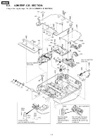
Страница 34: ...6 2 LOWER P C B SECTION Change from original page 194 18 3 LOWER P C B SECTION 34 KX FP105RS ...

