background image

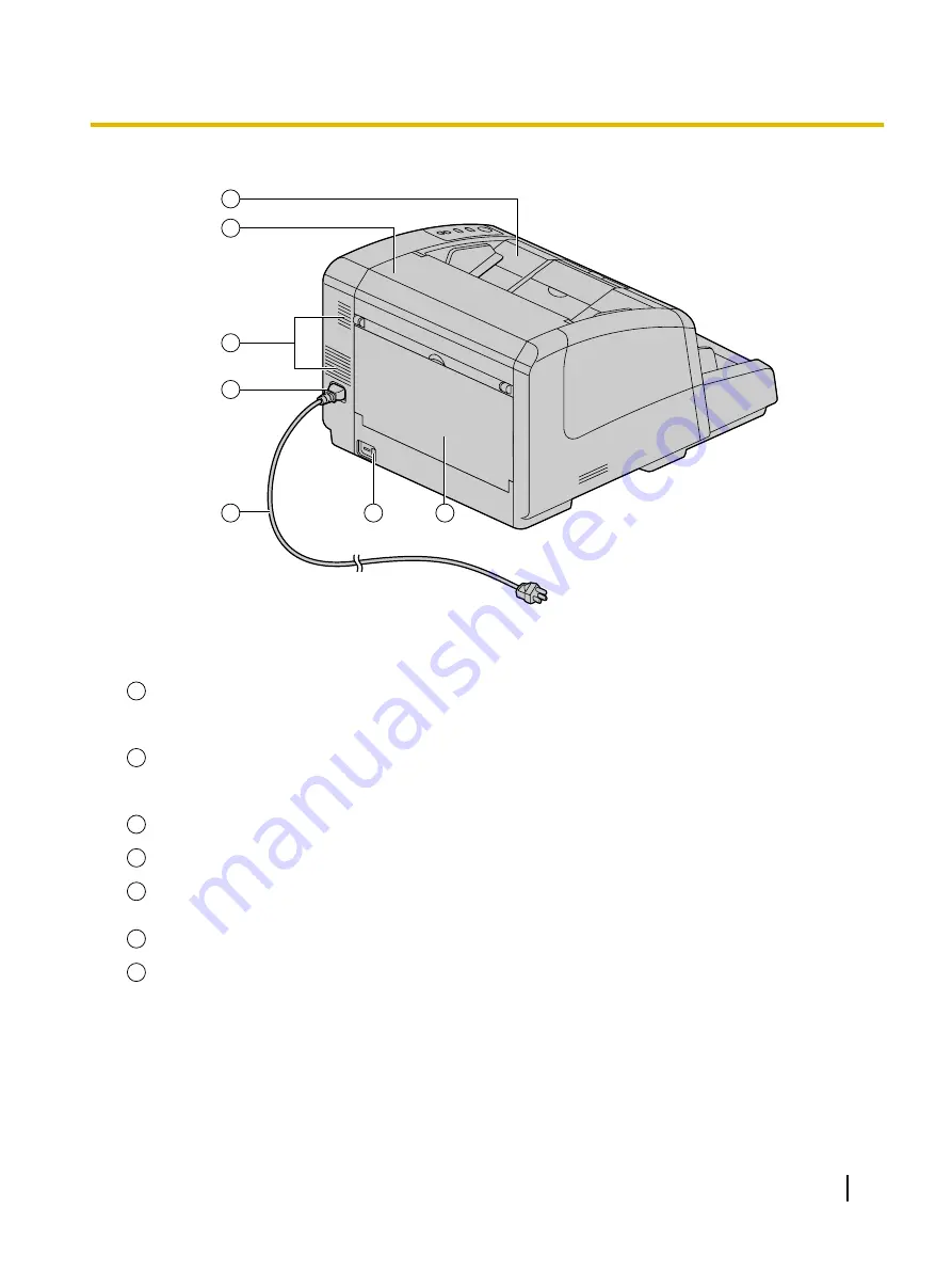
Rear

1

2

3

4

5

6

7

1

Pre-imprinter door (Exit tray)

You open this door when installing an imprinter unit (sold separately) or ink cartridge. For details
on installing an imprinter, refer to "Pre-imprinter" (page 67).

2

Post-imprinter door

You open this door when installing an imprinter unit (sold separately) or ink cartridge. For details
on installing an imprinter, refer to "Post-imprinter" (page 69).

3

Fan exhaust vent

4

AC inlet

5

Power cord

Plugs may vary in shape depending on country/area.

6

USB connector

7

Straight path tray

Opening and closing the straight path tray lets you change the exit direction. For details on the exit
direction, refer to "Selecting the Paper Path for Scanned Documents" (page 25) .

Operating Manual

15

Location of Controls

Содержание KV-S4085CL

Страница 1: ...ons please read the installation manual enclosed with this unit Please carefully read these instructions and the enclosed installation manual Keep all documentation in a safe place for future reference Model No KV S4085CL KV S4085CW KV S4065CL KV S4065CW Operating Manual High Speed Color Scanner ...

Страница 2: ...on scanning A4 size paper in portrait orientation Support for High efficiency Scanning Jobs This scanner has a Stapled document detection function which can automatically detect stapled documents and try to stop scanning before any damage is caused to the scanner This scanner is equipped with 3 ultrasonic sensors that can be turn on and off independently They are in 3 different locations left cent...

Страница 3: ...lity Abbreviations Windows refers to the Microsoft Windows operating system hereafter Windows Windows 2000 refers to the Microsoft Windows 2000 operating system hereafter Windows 2000 Windows XP refers to the Microsoft Windows XP operating system hereafter Windows XP Windows Vista refers to the Microsoft Windows Vista operating system hereafter Windows Vista The illustrations in this manual are of...

Страница 4: ...dows 2000 Windows XP Windows Vista Interface USB 2 0 Memory 1 GB or higher Hard Disk 5 GB or more free space is required Note The above system requirements may not satisfy the requirements of all operating systems The scanning speed differs depending on the host computer s operating environment or the application used Due to the slower speed of USB 1 1 it is recommended to use a USB 2 0 interface ...

Страница 5: ...ction manual may cause harmful interference to radio communications Operation of this equipment in a residential area is likely to cause harmful interference in which case the user will be required to correct the interference at his own expense FCC Warning To assure continued FCC compliance the user must use only shielded interface cable and the provided power supply cord Also any unauthorized cha...

Страница 6: ...27 Scanning Documents with Pages of Different Sizes 32 Using Control Sheets 39 About Printing Control Sheets 40 Changing the Scan Background Color 41 Switching the Reference Plate 41 Care and Maintenance 44 Clearing Paper Jams 44 Cleaning the Scanner 46 Outside of the Scanner 46 Inside of the Scanner 48 Cleaning the Rollers 49 Cleaning the Sensors and Image Sensor Covers 54 Replacement Parts and O...

Страница 7: ...Troubleshooting 77 Shading Adjustment 80 Repacking Instructions 81 Specifications 83 Index 85 Operating Manual 7 Table of Contents ...

Страница 8: ...h an unspecified current rating the unit or plug may emit smoke or become hot to the touch When you operate this product the power outlet should be near the product and easily accessible To ensure safe operation the power cord supplied must be inserted into a standard three prong AC outlet which is effectively grounded earthed through the normal wiring The fact that the equipment operates satisfac...

Страница 9: ...ice Operating the contaminated unit can cause fire or electric shock Do not open covers and do not attempt to repair the unit yourself Contact your dealer for service Do not alter the unit or modify any parts Alteration or modification can cause fire or electric shock During thunderstorms do not touch the unit and plug It may cause an electric shock Do not place the separation rollers or paper fee...

Страница 10: ... it by both side grips Dropping the unit can cause injury and damage to the unit Operating Safeguards If the unit falls down or gets damaged turn the unit off and unplug the power cord Otherwise it may cause fire or electric shock Do not place any liquids or heavy items on the unit Accidental spillage of liquid into the unit may cause severe damage If this occurs turn the unit off unplug the power...

Страница 11: ... YOUR PREMISES THEN THE FUSE SHOULD BE REMOVED AND THE PLUG CUT OFF AND DISPOSED OF SAFELY THERE IS DANGER OF SEVERE ELECTRICAL SHOCK IF THE CUT OFF PLUG IS INSERTED INTO ANY 13 AMP SOCKET If a new plug is to be fitted please observe the wiring cord as shown below If in any doubt please consult a qualified electrician WARNING THIS APPLIANCE MUST BE EARTHED IMPORTANT The wires in this mains lead ar...

Страница 12: ...d the CD ROM Roller Cleaning Paper Keep the roller cleaning paper out of reach of small children Do not store the roller cleaning paper in direct sunlight or in a place with a temperature over 40 C 104 F Only use the roller cleaning paper to clean the rollers and image sensor covers For details about the roller cleaning paper please refer to the Material Safety Data Sheet MSDS Please ask your Pana...

Страница 13: ...nstruments This list is not inclusive and no liability is assumed for either its completeness or accuracy In case of doubt contact your legal counsel Notice Install your machine near a supervised area to prevent illegal duplication from being made Security Notice The management of documents and scanned data is the responsibility of the user In particular pay attention to the following points Make ...

Страница 14: ...6 Document guides 7 Hopper 8 Hopper extension tray 9 Control Panel For details refer to Control Panel page 16 10 Error indicator Lights when an error occurs For details refer to About Status Indicators page 18 11 Front Door 12 Front door release 13 Power switch 14 Operating Manual L o c a t i o n o f C o n t r o l s Location of Controls ...

Страница 15: ... imprinter unit sold separately or ink cartridge For details on installing an imprinter refer to Post imprinter page 69 3 Fan exhaust vent 4 AC inlet 5 Power cord Plugs may vary in shape depending on country area 6 USB connector 7 Straight path tray Opening and closing the straight path tray lets you change the exit direction For details on the exit direction refer to Selecting the Paper Path for ...

Страница 16: ...o auto feeding or manual feeding 3 Paper thickness key Thickness Changes the paper thickness mode according to the document type See Changing the Paper Thickness Mode page 24 4 Start Stop key Start Stop If you set Wait Key for Manual Feed Mode 1 in your application software pushing this key starts scanning During scanning pushing this key stops scanning 16 Operating Manual Location of Controls ...

Страница 17: ...or Ready Shows the scanner s status For details see About Status Indicators page 18 1 For details on Manual Feed Mode refer to the RTIV Reference Manual or PIE Reference Manual Operating Manual 17 Location of Controls ...

Страница 18: ...2 seconds 2 On for 1 second and off for 3 seconds 3 On for 0 5 seconds and off for 0 5 seconds 4 Check the status of the scanner using User Utility For details about User Utility refer to the User Utility Reference Manual 5 The scanner will enter Standby mode when no operation is performed for 30 minutes to save power To use the scanner again restart it by pressing any one of the buttons for more ...

Страница 19: ...Turning on the Scanner Power 1 Set the power switch 1 of the scanner to ON 2 1 The ready indicator 2 lights green Operating Manual 19 O p e r a t i o n Operation ...

Страница 20: ...s loadable on the hopper Page thickness g m 20 5lbs 40 11 lbs 50 13 lbs 64 17 lbs 75 20 lbs 80 21 lbs 90 24 lbs 104 28 lbs 157 42 lbs 209 56 lbs Max number of sheets 500 350 320 300 250 240 210 180 120 100 The number of sheets listed above is a guideline for when the hopper height is set to Low and you are using fresh paper For details about the hopper height see Changing the Hopper Position page ...

Страница 21: ...ing direction For documents with mixed page sizes and thicknesses Document thickness The ratio of page thickness between the thickest and thinnest pages must be less than 1 5 Document size The ratio of width and height between the largest page and smallest page must be less than 1 5 Example If the smallest page is A4 size then the largest page can be up to A3 size and if the smallest page is A6 th...

Страница 22: ...l ink Non rectangular or irregularly shaped paper Notes about documents for scanning Depending on the paper type scanning results may be poor when you scan unacceptable documents or even documents that should be acceptable If a paper jam or double feeding occurs try scanning again after doing the following Clean the rollers and sensors Reduce the number of sheets of paper loaded on the hopper Chan...

Страница 23: ...amount of paper so that the hopper is at the same level as the feeder Setting the hopper position beforehand will shorten the scanning time Press the hopper key or to change the hopper position The hopper can be moved to the following three heights Hopper position Loadable number of sheets High 100 sheets Middle 200 sheets Low 300 sheets These guidelines are for using fresh 64 g m 17 lbs paper Ope...

Страница 24: ...When to use Thin 20 50 g m 5 13 lbs When scanning thin paper or paper with a rough surface such as NCR paper Normal 50 157 g m 13 42 lbs When scanning normal paper such as copier paper Thick 157 209 g m 42 56 lbs When scanning thick paper or paper with a smooth surface such as card stock Auto 20 157 g m 5 42 lbs When scanning a document mixing of paper thickness The scanning speed may slightly slo...

Страница 25: ...th Closed Front side Exit tray Opened Back side Straight path tray Note When scanning documents with a thickness of 0 2 0 6 mm 7 9 23 6 mils such as folded documents set to straight path If you are using the straight path ensure that there is enough space for long documents to exit If scanned documents are difficult to remove set the scanner with the front A facing right as shown in the illustrati...

Страница 26: ... before scanning Failing to do so can damage the unit document or both Curled documents may cause a paper jam or damaging the document therefore set the document flat before scanning When scanning important documents confirm that the number of scanned images matches the number of pages in the document Remove documents from the exit tray after they have been scanned 26 Operating Manual Operation ...

Страница 27: ...s Documents that have been stapled together or stacked together as in a file folder will need to be separated Fan the stack of documents to separate all the edges Hold both ends and bend the documents as shown in the illustration To flatten the documents hold firmly and pull them apart as shown in the illustration 1 2 3 Repeat these steps as necessary 3 Carefully align the documents 4 Adjust the d...

Страница 28: ...l they stop 1 2 Notice The height of the documents should not exceed the limit mark 2 on the document guide This may cause a paper jam or skewing The scanning width is different for the KV S4065CL KV S4085CL and KV S4065CW KV S4085CW KV S4065CL KV S4085CL 227 mm 8 9 in KV S4065CW KV S4085CW 302 mm 11 9 in 28 Operating Manual Operation ...

Страница 29: ...d 1 When scanning long sheets of paper Pull out the hopper extension tray 2 from the hopper 2 Note After placing the document on the hopper if you push the Start Stop key the hopper will rise to a position where pages can immediately start being fed Operating Manual 29 Operation ...

Страница 30: ...and raise the exit stopper 2 1 2 Note If you scan documents with the exit stopper 2 down documents may jam at the exit When scanning long sheets of paper Adjust the exit stopper 3 and extension sub tray 4 to match the size of the document 3 4 30 Operating Manual Operation ...

Страница 31: ... of the document Scanning direction Document 5 6 When scanning thin documents Slightly raise the exit sub stopper 7 The documents will exit smoothly since there is a smaller step at the exit 7 8 Open your scanning application 1 and scan the documents 1 The software RTIV and QuickScan Pro demo included with the scanner can be used for scanning the documents Operating Manual 31 Operation ...

Страница 32: ... key on the control panel to select auto feeding 2 Fan the documents Documents that have been stapled together or stacked together as in a file folder will need to be separated Fan the stack of documents to separate all the edges Hold both ends and bend the documents as shown in the illustration To flatten the documents hold firmly and pull them apart as shown in the illustration 1 2 3 Repeat thes...

Страница 33: ...3 Align the document pages along one side 2 2 2 2 4 Completely spread apart the document guides 1 1 Operating Manual 33 Operation ...

Страница 34: ...correctly 2 1 2 3 Notice The height of the documents should not exceed the limit mark 3 on the document guide This may cause a paper jam or skew Depending on the types of paper the document may not be fed smoothly In such case reduce the number of sheets of the document The scanning width is different for the KV S4065CL KV S4085CL and KV S4065CW KV S4085CW KV S4065CL KV S4085CL 227 mm 8 9 in KV S4...

Страница 35: ...ace slide the left document guide 2 to where you will place the left edge of the document 2 2 1 7 While keeping the left document guide 1 in place slide the right document guide 2 to match the width of the document 2 2 1 Operating Manual 35 Operation ...

Страница 36: ...er if you push the Start Stop key the hopper will rise to a position where pages can immediately start being fed 8 Slide the exit guides 1 to match the width of the document guides 2 and raise the exit stopper 3 2 1 3 2 Note If you scan documents with the exit stopper 3 down documents may jam at the exit 36 Operating Manual Operation ...

Страница 37: ...the largest document page 4 5 2 When scanning short sheets of paper When scanning documents like the one shown in the figure below fully raise the exit sub stopper 6 and adjust the extension sub tray 7 to match the size of the document Scanning direction Document 6 7 Operating Manual 37 Operation ...

Страница 38: ... step at the exit 8 9 Open your scanning application 1 and scan the documents 1 The software RTIV and QuickScan Pro demo included with the scanner can be used for scanning the documents Note By fully spreading the left and right document guides you can reestablish their original center position 38 Operating Manual Operation ...

Страница 39: ...D ROM B S i m p l e x A Documents Control sheet Code Documents Control sheet functions Simplex Duplex Binary 256 level gray Color Dynamic Threshold Dither Error diffusion Function 1 9 Separation Sheet Note Multiple control sheets can be used To use control sheet functions your scanning application must support control sheets When using control sheets refer to the instruction manual of your scannin...

Страница 40: ...ference Manual Printing control sheets Note In order to print control sheets Adobe Reader must been installed on your computer Refer to the instruction manual for your printer for details about changing print settings 1 Insert the CD ROM into the CD DVD driver on your computer If you have a feature called Autorun activated the installation process will start automatically The setup window will app...

Страница 41: ...e Set the front reference plate and rear reference plate to the same color If the front and rear settings are different then documents will not be scanned correctly Switching the Reference Plate 1 Set the power switch 1 of the scanner to OFF Remove any documents from the exit tray 1 2 Pull the front door release 1 towards you and open the front door 2 1 2 Operating Manual 41 Operation ...

Страница 42: ...3 Move the reference plate lever R 1 and the reference plate lever F 2 1 2 Move the levers to the color you want to change the background to White Black 42 Operating Manual Operation ...

Страница 43: ...4 Close the front door Push both sides of the front door down slowly until it clicks into place 5 Set the power switch of the scanner to ON Operating Manual 43 Operation ...

Страница 44: ...ollowing procedure CAUTION The image sensor covers may be very hot after scanning a lot of documents Removed the jammed sheet after the image sensor covers temperature has cooled 1 Pull the front door release 1 towards you and open the front door 2 Remove any documents from the exit tray 1 2 44 Operating Manual C a r e a n d M a i n t e n a n c e Care and Maintenance ...

Страница 45: ...nside of the scanner towards the front When a paper jam occurs at the exit slot Pull the jammed paper from the exit slot 1 towards the front 1 3 Close the front door Push both sides of the front door down slowly until it clicks into place Operating Manual 45 Care and Maintenance ...

Страница 46: ...ives or surfactants for cleaning the outside of the scanner Clean the scanner at least once a month 1 Set the power switch 1 of the scanner to OFF 1 2 Clean the cover with a soft cloth The document feeder 1 and exit slot 2 get dirty easily Make sure to clean them 2 1 46 Operating Manual Care and Maintenance ...

Страница 47: ...3 Remove dirt and dust from the fan exhaust vent 1 with a brush 1 Operating Manual 47 Care and Maintenance ...

Страница 48: ...ler cleaning paper 1 Notice Keep the roller cleaning paper out of reach of small children Do not store the roller cleaning paper in direct sunlight or in a place with temperature over 40 C 104 F Only use the roller cleaning paper to clean the rollers and image sensor covers For details about the roller cleaning paper please refer to the Material Safety Data Sheet MSDS Please ask your Panasonic sal...

Страница 49: ...can cause injury Notched section A Image sensor cover Straight path tray The image sensor covers may be very hot after scanning a lot of documents Clean the image sensor covers after the temperature has cooled 1 Set the power switch of the scanner to OFF 2 Pull the front door release 1 towards you and open the front door 2 1 2 Operating Manual 49 Care and Maintenance ...

Страница 50: ...e arrows in the illustration If you wipe too hard you may damage or misalign the roller For instructions on how to remove the double feed prevention roller see Replacing the Double Feed Prevention Roller page 62 Wipe dirt off of the other rollers in the directions indicated by the arrows in the illustration Use your finger to rotate the roller and wipe dirt off of the entire surface of the roller ...

Страница 51: ...ation of Rollers 1 2 3 1 Paper feed rollers 2 Separation rollers 3 Free rollers 4 5 4 Drive rollers 5 Double feed prevention roller Left side view 6 6 Drive rollers Operating Manual 51 Care and Maintenance ...

Страница 52: ...7 7 7 Free rollers 4 Close the front door Push both sides of the front door down slowly until it clicks into place 5 Set the power switch of the scanner to ON 52 Operating Manual Care and Maintenance ...

Страница 53: ...n User Utility to 0 Start User Utility and in the window click the Clear Counter button 2 for After Clean Roller 1 to reset to counter to 0 For details refer to the User Utility Reference Manual 1 2 Operating Manual 53 Care and Maintenance ...

Страница 54: ...hed section can cause injury Notched section A Image sensor cover Straight path tray The image sensor covers may be very hot after scanning a lot of documents Clean the image sensor covers after the temperature has cooled 1 Set the power switch of the scanner to OFF 2 Pull the front door release 1 towards you and open the front door 2 1 2 54 Operating Manual Care and Maintenance ...

Страница 55: ...veyor indentations 2 and blow off dirt as shown in the illustration below 1 2 Location of Sensors 5 4 4 3 6 7 3 Waiting sensor 4 Skew sensors 5 Double feed detectors For the KV S4065CL KV S4065CW there is only 1 double feed detector in the center 6 Starting sensor 7 Image sensor cover F 9 10 8 8 Double feed detectors For the KV S4065CL KV S4065CW there is only 1 double feed detector in the center ...

Страница 56: ...Left side view 11 11 Paper jam sensor Location of Reflectors 12 13 12 Reflectors 13 Indentations Left side view 14 14 Indentations 56 Operating Manual Care and Maintenance ...

Страница 57: ... off any dirt from the slip detect sensor 2 while rotating it 2 1 5 Close the front door Push both sides of the front door down slowly until it clicks into place 6 Set the power switch of the scanner to ON Operating Manual 57 Care and Maintenance ...

Страница 58: ...mbers on documents Includes 1 ink cartridge For instructions on installation see Installing the Imprinter Unit page 67 Note To purchase replacement parts or optional units contact the store where you purchased the scanner When to replace parts We recommend replacing the paper feed rollers separation rollers and double feed prevention roller after scanning 400 000 sheets of paper 400 000 sheets is ...

Страница 59: ...Feed Rollers and Separation Rollers WARNING Do not place the separation rollers or paper feed rollers where small children can reach them There is a danger that the rollers may be swallowed In the event that you think they have been swallowed contact a doctor immediately 1 Set the power switch 1 of the scanner to OFF and unplug the power cord 1 2 Pull the front door release 1 towards you and open ...

Страница 60: ... the paper feed rollers 2 and separation rollers 3 2 3 1 5 Take out the new paper feed rollers and separation rollers in the optional Roller exchange kit KV SS033 6 Align the shaft and the roller hole and install the rollers on the shaft until they click into place Install both the paper feed rollers 1 and separation rollers 2 1 2 60 Operating Manual Replacement Parts and Optional Units ...

Страница 61: ...ed roller cover correctly If the paper feed roller cover is not closed completely when closing the front door the paper feed roller cover may break 8 Close the front door Push both sides of the front door down slowly until it clicks into place 9 Plug in the power cord and set the power switch of the scanner to ON Operating Manual 61 Replacement Parts and Optional Units ...

Страница 62: ...tion roller cover cannot be opened if the hopper is not in the Low position For details on adjusting the hopper s height see Changing the Hopper Position page 23 1 Set the power switch 1 of the scanner to OFF and unplug the power cord 1 2 Pull the front door release 1 towards you and open the front door 2 1 2 62 Operating Manual Replacement Parts and Optional Units ...

Страница 63: ...ds you by using the indent 1 1 4 Remove the double feed prevention roller 1 in the direction of the arrow 1 5 Take out the new double feed prevention roller in the optional Roller exchange kit KV SS033 Operating Manual 63 Replacement Parts and Optional Units ...

Страница 64: ...2 grooves on the shaft Align the grooves with the U shaped section on the roller mount to install it 1 1 2 Notice After you install the double feed prevention roller make sure that the shaft will not rotate or move If the groove is not properly inserted in the roller mount it may cause double feeding or a paper jam 64 Operating Manual Replacement Parts and Optional Units ...

Страница 65: ...ks into place If the double feed prevention roller cover is not closed correctly when the front door is closed the double feed prevention roller cover may break 8 Close the front door Push both sides of the front door down slowly until it clicks into place 9 Plug in the power cord and set the power switch of the scanner to ON Operating Manual 65 Replacement Parts and Optional Units ...

Страница 66: ...ility to 0 Start User Utility and in the window click the Clear Counter button 2 for After Replace Roller 1 to reset the counter to 0 For details refer to the User Utility Reference Manual 1 2 66 Operating Manual Replacement Parts and Optional Units ...

Страница 67: ...rinter prints on the face of the document before scanning The printed material will also be scanned The post imprinter prints on the rear of the document after scanning The printed material will not be scanned Pre imprinter 1 Set the power switch 1 of the scanner to OFF 1 2 Open the pre imprinter door 1 1 Operating Manual 67 Replacement Parts and Optional Units ...

Страница 68: ... and insert the pins 3 and 4 into the guides until they are locked by the springs 1 2 3 4 3 4 1 2 4 Connect the cable Notice Be sure to correctly match the rib with the slot prior to inserting the connector 68 Operating Manual Replacement Parts and Optional Units ...

Страница 69: ...ower switch of the scanner to ON Note For details on installing an ink cartridge refer to Installing the Ink Cartridge page 72 Post imprinter 1 Set the power switch 1 of the scanner to OFF 1 Operating Manual 69 Replacement Parts and Optional Units ...

Страница 70: ...2 Open the post imprinter door 3 Connect the cable Notice Be sure to correctly match the rib with the slot prior to inserting the connector 70 Operating Manual Replacement Parts and Optional Units ...

Страница 71: ...s and insert the pins 2 on both sides into the guides until they are locked by the springs 3 1 2 1 2 3 5 Close the post imprinter door 6 Set the power switch of the scanner to ON Note For details on installing an ink cartridge refer to Installing the Ink Cartridge page 72 Operating Manual 71 Replacement Parts and Optional Units ...

Страница 72: ...stalling the Ink Cartridge Install the ink cartridge in the imprinter 1 Set the power switch 1 of the scanner to OFF 1 2 Remove the protective tape 72 Operating Manual Replacement Parts and Optional Units ...

Страница 73: ...e position Notice When using the pre imprinter adjust the position following the label on the scanner 4 Insert the ink cartridge into the carriage 5 Lock the ink cartridge adjustment lever 1 1 Operating Manual 73 Replacement Parts and Optional Units ...

Страница 74: ...carriage to the ink cartridge exchange position Notice When using the pre imprinter adjust the position following the label on the scanner 3 Pinch the ink cartridge adjustment lever 1 and lift it 1 4 Remove the ink cartridge 1 1 74 Operating Manual Replacement Parts and Optional Units ...

Страница 75: ...en line 1 The green line 1 indicates the printing position Printing is not available in any other position 2 1 3 Adjusting the post imprinter printing position 1 Move the carriage to the desired printing position and align the indicator 2 with the mark 1 The mark 1 indicates the printing position Printing is not available in any other position 2 1 Operating Manual 75 Replacement Parts and Optional...

Страница 76: ... Document size Center Note The above figure shows the possible printing positions when using the pre imprinter which prints on the front of the document When using the post imprinter which prints on the back of the document the printing positions are flipped horizontally Printing Printing can be set from the RTIV program and the TWAIN and ISIS drivers For details refer to the RTIV Reference Manual...

Страница 77: ...m the computer and then install the software again Refer to Installing the Software in the Installation Manual The USB interface of the computer is not installed correctly Check the computer whether the USB interface of your computer is installed correctly using the device manager s property The scanner is connected via USB hub Do not connect via USB hub There is a problem with the USB cable Use t...

Страница 78: ...le type and thickness page 20 and scan the copy The length of the paper is too short Make a copy of the document on paper of an acceptable size page 20 and scan the copy The feeding method is set to manual Set the feeding method to auto with the ADF select key Page 16 The paper thickness mode is not appropriate for the documents Change the paper thickness mode Page 24 The document is not aligned c...

Страница 79: ...nes appear on the scanned document The image sensor covers are dirty Clean the image sensor covers F and B Page 54 The scanning density is uneven The image sensor covers are dirty Clean the image sensor covers F and B Page 54 The quantity distribution of light varies Adjust shading Page 80 The color of the scanned document is extremely different from the original document The settings of the compu...

Страница 80: ...nning shading adjustment thoroughly clean the image sensor cover F image sensor cover B conveyors in the scanning area and all rollers If you perform shading adjustment while these parts are dirty lines will appear on scanned images Shading adjustment procedure 1 Start the User Utility 2 Click User Shading on the main menu and operate as the image display dictates Note For further details refer to...

Страница 81: ...e original carton and all of the original packing materials The scanner should be handled in the correct horizontal position Required Materials Original scanner carton and packing materials Shipping tape and scissors 1 Unplug the power cord from the outlet and remove the power cord and USB cable from the scanner 2 Return the exit stopper and extension sub tray to their original non extended positi...

Страница 82: ...scanner 1 2 3 5 6 4 1 Joint 2 USB cable 3 Power cord 4 Double feed prevention roller 5 Blower 6 Drivers Utilities Manuals CD ROM Installation Manual Shading paper Roller cleaning paper 82 Operating Manual Appendix ...

Страница 83: ...s min A4 Approx 160 images min Simplex Letter Approx 100 pages min A4 Approx 100 pages min Duplex Letter Approx 200 images min A4 Approx 200 images min Resolution 100 600 dpi 1 dpi step Optical 600 dpi Main and Sub feeding directions Tonal gradation Binary Grayscale 8 bit Color MultiStream Binary Grayscale Binary Color Image control Image emphasis Dynamic threshold Automatic separation Invert Whit...

Страница 84: ...ess AC 100 240 V 36 W or less AC 100 240 V Sleep 2 W or less AC 100 240 V 2 W or less AC 100 240 V Standby 0 5 W or less AC 100 240 V 0 5 W or less AC 100 240 V Operating Environment Temperature 15 30 C 59 86 F Humidity 20 80 RH Storage Environment Temperature 0 40 C 32 104 F Humidity 10 80 RH 1 The scanning speed differs depending on the host computer operating system application the data quantit...

Страница 85: ... Hard disk 4 Hopper 14 Hopper capacity 83 Hopper extension tray 14 Hopper key 16 Hopper position 23 I Image control 83 Image sensor cover B 55 Image sensor cover F 55 Imprinter unit 58 67 Ink cartridge 58 72 Interface 4 J Joint 82 L Limit Mark 28 34 M Memory 4 O Operating Environment 84 Operating system 4 Optional units 58 P Paper 83 Paper jams 44 Paper thickness key 16 Paper thickness mode 24 Pos...

Страница 86: ...per jam sensor 56 Paper sensor 55 Skew sensors 55 Slip detect sensor 57 Starting sensor 55 Waiting sensor 55 Shading adjustment 80 Shading paper 82 Specifications 83 Start Stop key 16 Storage Environment 84 Straight path tray 15 System Requirements 4 T Tonal gradation 83 Troubleshooting 77 U USB cable 82 USB connector 15 User Utility 53 66 W Weight 84 86 Operating Manual Index ...

Страница 87: ...PJQXC0135WA KK0408YR4082 Panasonic System Networks Co Ltd 2008 Web Site http www panasonic net ...

Отзывы: