


4
---
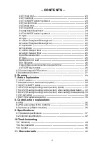
CONTENTS
---
1. Model number
1.1 Explanation of model number ---------------------------------------------------- 6
1.2 Rated input ---------------------------------------------------------------------------- 7
1.3 How to read the rated label ------------------------------------------------------- 7
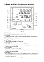
2. Name and functions of the sections
------------------------------------ 8
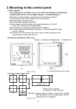
3. Mounting to the control panel
3.1 Site selection ----------------------------------------------------------------------- 10
3.2 External dimensions (Unit: mm) ----------------------------------------------- 10
3.3 Panel cutout (Unit: mm) ---------------------------------------------------------- 10
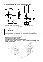
3.4 CT (current transformer) external dimensions (Unit: mm) --------------- 11
3.5 Mounting ----------------------------------------------------------------------------- 11
4. Wiring
4.1 Terminal arrangement ------------------------------------------------------------ 12
4.2 Wiring examples ------------------------------------------------------------------- 13
5. Setup
5.1 Operation flowchart --------------------------------------------------------------- 16
5.2 Main setting mode
SV1 ------------------------------------------------------------------------------------- 18
SV2 ------------------------------------------------------------------------------------- 18
5.3 Output MV indication -------------------------------------------------------------- 18
5.4 Sub setting mode
AT/Auto-reset ------------------------------------------------------------------------ 18
OUT1 proportional band ---------------------------------------------------------- 19
OUT2 proportional band ---------------------------------------------------------- 19
Integral time -------------------------------------------------------------------------- 19
Derivative time ---------------------------------------------------------------------- 19
ARW (Anti-reset windup) --------------------------------------------------------- 19
OUT1 proportional cycle ---------------------------------------------------------- 19
OUT2 proportional cycle --------------------------------------------------------- 19
A1 value ------------------------------------------------------------------------------ 20
A2 value ------------------------------------------------------------------------------ 20
HB (Heater burnout alarm) value ---------------------------------------------- 20
5.5 Auxiliary function setting mode 1
Set value lock ----------------------------------------------------------------------- 21
SV high limit ------------------------------------------------------------------------- 21
SV low limit -------------------------------------------------------------------------- 21
Sensor correction ------------------------------------------------------------------ 21
Communication protocol --------------------------------------------------------- 21
Instrument number ---------------------------------------------------------------- 21
Communication speed ------------------------------------------------------------ 21
Parity ---------------------------------------------------------------------------------- 22
Stop bit -------------------------------------------------------------------------------- 22
5.6 Auxiliary function setting mode 2
Input type ----------------------------------------------------------------------------- 22
Scaling high limit ------------------------------------------------------------------- 23
Scaling low limit -------------------------------------------------------------------- 23
Decimal point place --------------------------------------------------------------- 23
PV filter time constant ------------------------------------------------------------ 23