39
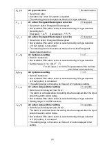
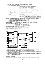
• ON/OFF action: When OUT1 proportional band is set to 0
OUT1 proportional band (P)
Thermocouple: 0 to 1000
(0 to 2000 )
RTD: 0.0 to 999.9
(0.0 to 999.9 )
DC current, voltage: 0.0 to 100.0%
(ON/OFF action when set to 0
(
), 0.0
(
) or 0.0%)
Integral time (I)
: 0 to 1000sec (Off when set to 0)
Derivative time (D)
: 0 to 300sec (Off when set to 0)
OUT1 proportional cycle : 1 to 120sec (Not available for DC current output type)
ARW
: 0 to 100%
OUT1 hysteresis
: Thermocouple, RTD input: 0.1 to 100.0
( )
DC current, voltage input: 1 to 1000 (The placement
of the decimal point follows the selection)
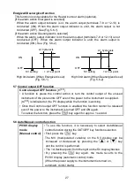
SV1/SV2 external selection
: SV1 and SV2 can be selected by external contact.
Contact open between terminals 14 and 17 : SV1
Contact closed between terminals 14 and 17: SV2
Contact current: 6mA
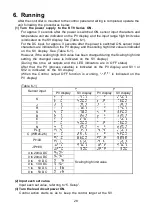
Supply voltage
: 100 to 240V AC
50/60Hz,
24V AC/DC
50/60Hz
Allowable voltage fluctuation range
100 to 240V AC : 85 to 264V AC
24V AC/DC
: 20 to 28V AC/DC
Ambient temperature
: 0 to 50
(32 to 122 )
Ambient humidity
: 35 to 85%RH (no condensation)
Power consumption
: Approx. 8VA
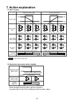
Circuit insulation configuration
• When OUT1 is non-contact voltage or DC current output type and OUT2 is Non-
contact voltage or DC current output type, A is not insulated from B.
• When OUT1 is non-contact voltage or DC current output type, A is not insulated from
C, and A is not insulated from D.
When OUT2 is non-contact voltage or DC current output type, B is not insulated from
C, and B is not insulated from D.
Insulation resistance
10M
or more, at 500V DC for other combinations except the above mentioned
OUT1
A
Power
source
CT input
Input
Ground
Insulated
OUT2 or Heater
burnout alarm output
3
1
2
5
4
9
8
7
6
10
20
18
19
16
15
A1 output
A2 output or Heater
burnout alarm output
13
12
11
14
17
C
o
m
m
u
n
ic
a
tio
n
SV2
17
14
B
C
D

