


14
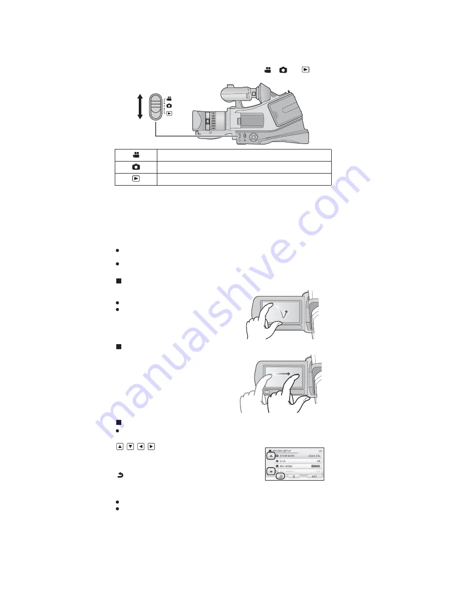
Selecting a mode
Change the mode to recording or playback.
Operate the mode switch to change the mode to
,
or
.
Motion picture recording mode
Still picture recording mode
Playback mode
You can operate by directly touching the LCD monitor (touch screen) with your finger.
It is easier to use the stylus pen (supplied) for detailed operation or if it is hard to operate with
your fingers.
The unit supports both operations using the cursor buttons and operations using the touch
screen. Select the optimal method according to the situation.
In this operating instructions, the majority of functions are described on the basis of
operations using the cursor buttons.
Touch
Touch and release the touch screen to select
icon or picture.
Touch the centre of the icon.
Touching the touch screen will not operate
while you are touching another part of the
touch screen.
Drag
Move your finger while pressing on the touch
screen. Can be used during direct playback.
About the operation icons
To operate the following icons using the cursor buttons, select the desired icon using the
cursor buttons and then press the button in the centre. (Excluding some functions)
/
/
/
:
These icons are used to switch the menu and
thumbnail display page, for item selection and setting
etc.
:
This icon is used to return to the previous screen such
as when setting menus.
How to use the touch screen
Do not touch the LCD monitor with hard pointed tips, such as ball point pens.
Perform the touch screen calibration when the touch is not recognised or wrong location is
recognised.
Содержание HDC-MDH1GC
Страница 9: ...9 4 Specifications ...
Страница 10: ...10 ...
Страница 13: ...13 ...
Страница 21: ...21 8 3 2 Removal of the Hood ND Case Unit and Focus Ring Fig D2 8 3 3 Removal of the Side Case R Unit Fig D3 ...
Страница 22: ...22 8 3 4 Removal of the Speaker Fig D4 8 3 5 Removal of the Side R OP P C B Unit Fig D5 Fig D6 ...
Страница 23: ...23 8 3 6 Removal of the Side R Int P C B Unit Fig D7 Fig D8 8 3 7 Removal of the Lens Unit Fig D9 ...
Страница 24: ...24 Fig D10 8 3 8 Removal of the Lens Int P C B Unit and Main P C B Unit Fig D11 Fig D12 ...
Страница 25: ...25 8 3 9 Removal of the SD Holder P C B Unit Fig D13 8 3 10 Removal of the Jack P C B Unit Fig D14 ...
Страница 27: ...27 Fig D18 8 3 14 Removal of the Handle Zoom P C B Unit Fig D19 Fig D20 ...
Страница 28: ...28 8 3 15 Removal of the EVF Case Unit Fig D21 Fig D22 8 3 16 Removal of the EVF Angle Adj Case Unit Fig D23 ...
Страница 29: ...29 8 3 17 Removal of the EVF Unit and EVF Int P C B Unit Fig D24 Fig D25 ...
Страница 31: ...31 Fig D30 8 3 21 Removal of the Front P C B Unit Fig D31 Fig D32 8 3 22 Removal of the LCD Case Unit Fig D33 ...
Страница 32: ...32 Fig D34 8 3 23 Removal of the LCD Unit and Moni tor P C B Unit Fig D35 ...
Страница 33: ...33 Fig D36 8 3 24 Removal of the MOS Unit and IR Fil ter Fig D37 ...
Страница 34: ...34 8 3 25 Removal of the Focus Motor Fig D38 8 3 26 Removal of the Zoom Motor Fig D39 ...
Страница 66: ...S 29 ...
Страница 81: ...S 44 ...
Страница 98: ...S 61 S7 6 LCD Section B87 16 98 133 132 101 100 99 81 97 96 B86 B88 84 ...


