9-14
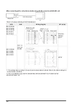
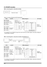
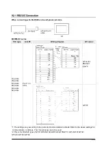
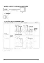
When connecting with self-produced cable using a RJ45 connector
RJ45 modular port
Port 1 viewed from the front of the module (socket side)
MICRO-EH series
PLC type
Link I/F
Wiring diagram
GT series
14 points
20 points
23 points
28 points
40 points
64 points
Port 1 on
CPU
GT series
RS232C
type*2
GT707
*1:1 The settings vary according to the ports and communication methods. Refer to the above settings
for communication conditions. The 10-point type cannot be used.
*2: This is for RS232C type of GT01/GT02/GT02L/GT03-E/GT05/GT11/GT12/GT21/GT32/
GT32-E/GT703/GT704.
Содержание GT series
Страница 6: ...iv...
Страница 13: ...Chapter 1 Connection With Mitsubishi PLCs...
Страница 38: ...1 26...
Страница 39: ...Chapter 2 Connection With Omron PLCs...
Страница 62: ...2 24...
Страница 63: ...Chapter 3 Connection With Toshiba Machine PLCs...
Страница 67: ...Chapter 4 Connection With Rockwell Automation Allen Bradley PLCs...
Страница 73: ...Chapter 5 Connection With Siemens PLCs...
Страница 76: ...5 4 5 1 2 RS422 Connection CPU Wiring diagram GT series CPU212 CPU214 CPU215 CPU216 CPU222 RS422 RS485 type...
Страница 77: ...Chapter 6 Connection With LS Industrial Systems PLCs...
Страница 80: ...6 4...
Страница 81: ...Chapter 7 Connection With Yokogawa PLCs...
Страница 86: ...7 6...
Страница 87: ...Chapter 8 Connection With Keyence PLCs...
Страница 109: ...Chapter 9 Connection With Hitachi PLCs...
Страница 129: ...Chapter 10 Connection in Modbus RTU Mode...


