


-17-
5. Move the cursor to the RGB SYNC parameter.
6. Select 4.0V or 0.3V according to the RGB monitor
input level.
Horizontal Phase Adjustment (H PHASE)
1. Move the cursor to H PHASE. The cursor starts
blinking.
2. Supply the video output signal of the camera to be
adjusted and the reference gen-lock input signal to
a dual-trace oscilloscope.
3. Set the oscilloscope to the horizontal sync portion
on the oscilloscope.
4. Adjust the horizontal phase by pressing
A
or
B
.
The adjustable range is 0-1.5
µ
s.
Note:
To reset H PHASE to the values preset at the
factory, press
A
and
B
simultaneously. The H
PHASE is reset to the factory setting.
Subcarrier Coarse Phase Adjustment (SC COARSE)
1. Move the cursor to the SC COARSE parameter on
the SYNC menu. The cursor starts blinking.
2. Press
A
or
B
to match the colour of the camera's
video signal, when observed at the output of the
Special Effects Generator (SEG) or Switcher, as
closely as possible to the colour of the original
scene. (The SC COARSE adjustment can be incre-
mented in steps of 90 degrees (4 steps) by press-
ing
A
or
B
.)
Note:
After the fourth step, the adjustment returns to
the first step.
Subcarrier Fine Phase Adjustment (SC FINE)
1. Move the cursor to SC FINE on the SYNC menu. The
cursor starts blinking.
2. Press
A
or
B
to match the colour of the camera's
video signal, when observed at the output of the
Special Effects Generator (SEG) or Switcher, as
closely as possible to the colour of the original
scene.
The SC FINE adjustment has a range of 90 degrees
of colour shift.
Notes:
• When the “I” cursor reaches the “+” end, it jumps
back to “–”. At the same time, SC COARSE is incre-
mented by one step to enable a continuous adjust-
ment. The reverse takes place when the “I” cursor
reaches the “–” end.
For more accurate adjustment, supply both the
original camera video output signal and the effect
output video signal (program output video signal)
of the special effects generator (SEG) to a vec-
torscope and compare the chroma phase of both
signals.
• To reset SC FINE to the values preset at the facto-
ry, press
A
and
B
simultaneously. The SC FINE is
reset to the factory setting.
6-3. VS Gen-lock Mode (EXT(VS))
1. Move the cursor to the SYNC parameter.
2. Connect the coaxial cable for the composite sync
or composite B/W video signal to the gen-lock input
connector.
3. Confirm that the INT parameter changed to
EXT(VS) on the menu.
Caution:
The gen-lock input signal should meet the
CCIR specifications and should not contain jit-
ter, such as a VTR playback signal, as it could
disturb synchronization.
4. After confirming that the cursor is on EXT (VS),
press the PAGE button. The phase adjustment
menu appears on the monitor screen.
5. Move the cursor to the RGB SYNC parameter.
6. Select 4.0V or 0.3V according to the RGB monitor
input level.
7. Move the cursor to H PHASE. The cursor starts
blinking.
1 (1 - - 4): 0 degrees
2 (1 - - 4): 90 degrees
3 (1 - - 4): 180 degrees
4 (1 - - 4): 270 degrees
** SET UP **
CAMERA ID *OFF
FLD/FRM FLD
ELC *OFF
SHUTTER OFF
GAIN AUTO
SYNC *EXT(VS)
BLACK BAL ABC
SCENE FILE *SCENE1
END
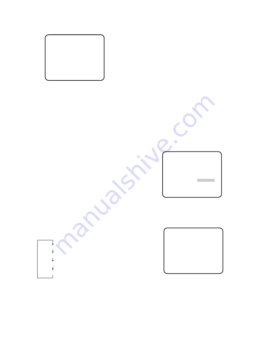
** SYNC **
RGB SYNC 0.3V
H PHASE -....I....+
RET END
** SYNC **
RGB SYNC 0.3V
H PHASE -....I....+
SC COARSE 1(1--4)
SC FINE -I........+
RET END
4. After confirming that the cursor is on EXT(VBS),
press the PAGE button. The SYNC menu appears
on the monitor screen.