


Ge
tting star
te
d
RQT67
3
0
4
Connection
Before connection
≥
Disconnect the AC mains lead.
≥
Turn off all equipment and read the appropriate operating instructions.
≥
The equipment connections described are examples.
≥
Peripheral equipment and optional cables sold separately unless
otherwise indicated.
This page explains how to connect the unit to a television and set it up so you hear the audio through the television’s speakers. To get the full benefit
from the powerful multi-channel audio found on DVDs, you should connect an amplifier and speakers.
To enjoy progressive video
1. Connect to the component video input terminals on a 480P
compatible television (
➜
above). (Video will not be displayed
correctly if connected to an incompatible television.)
2. In QUICK SETUP, set “Video Out (AV/Component)” to “Y PB
PR”, and set “Progressive Out (Component)” to “Enable
(NTSC Disc Only)” (
➜
page 5).
3. When playing NTSC discs, change video output mode to
“480P” (
➜
page 14).
≥
If the unit is connected to the television through VIDEO OUT, S
VIDEO OUT or SCART (AV) terminal, output will be interlace,
irrespective of the settings.
≥
All televisions manufactured by Panasonic and that have 480P input
connectors are compatible. Consult the manufacturer if you have
another brand of television.
∫
Power Connection
Conserving power
This unit consumes a small amount of power, even when it is turned off
(approx. 2.8 W).
To save power when the unit is not to be used for a long time, unplug it
from the household mains socket.
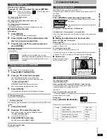
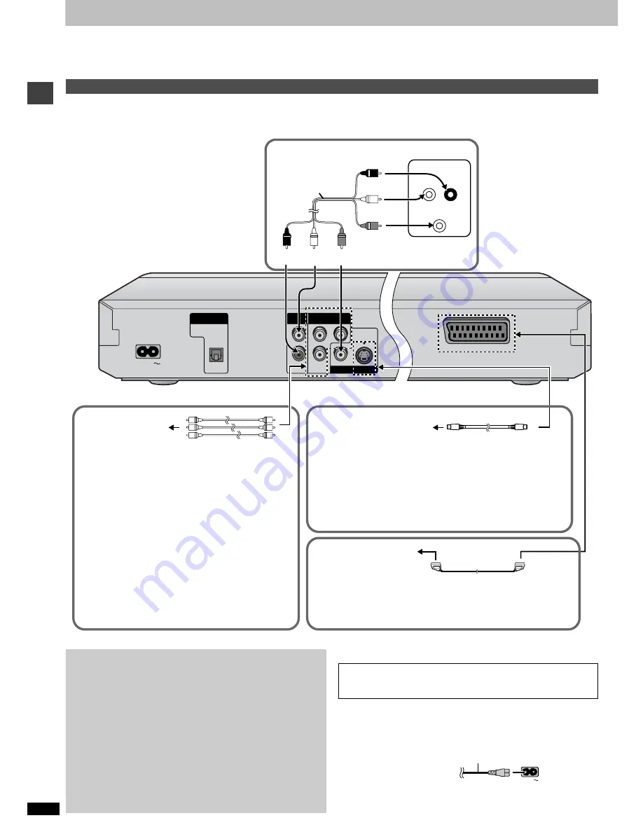
Connection to a television
DIGITAL AUDIO OUT
(PCM/BITSTREAM)
AUDIO
OUT
COMPONENT VIDEO OUT
(480P/480I/576I)
VIDEO OUT
S VIDEO OUT
OPTICAL
AC IN
L
Y
R
P
R
P
B
A V
AUDIO IN
L
VIDEO IN
R
Television
Audio/video cable
(included)
red
white
yellow
red
white yellow
∫
Basic connection
COMPONENT VIDEO OUT terminal
These terminals can be used for either interlace or
progressive output and provide a purer picture than the S
VIDEO OUT terminal. Connection using these terminals
outputs the colour difference signals (P
B
/P
R
) and luminance
signal (Y) separately in order to achieve high fidelity in
reproducing colours.The description of the component video
input terminals depends on the television or monitor (e.g. Y/
P
B
/P
R
, Y/B-Y/R-Y, Y/C
B
/C
R
). Connect to terminals of the
same colour.
≥
When making this connection, ensure you connect the
audio cables to the corresponding audio input terminals on
the television, and set “Video Out (AV/Component)” to “Y
PB PR” from Quick Setup (
➜
page 5).
Video cable (not included)
Television’s
COMPONENT VIDEO
IN terminals
∫
For better pictures
S video cable (not included)
S VIDEO OUT terminal
The S video terminal achieves a more vivid picture than the VIDEO OUT
terminal by separating the chrominance (C) and luminance (Y) signals.
(Actual results depend on the television.)
≥
When making this connection, ensure you connect the audio cables to
the corresponding audio input terminals on the television.
Television’s S VIDEO IN
terminal
21-pin SCART cable
(not included)
SCART (AV) terminal
To improve picture quality, you can change the video signal output from
the SCART (AV) terminal from “Video” to either “S-Video” or “RGB” to suit
the type of television your are using. Set “Video Out (AV/Component)” to
“S-Video” or “RGB” from Quick Setup (
➜
page 5).
Television’s
SCART IN terminal
Do not place the unit on amplifiers or
equipment that may become hot.
The heat can damage the unit.
Connect your unit directly to your
television.
Do not connect the unit through your video
cassette recorder when setting up your home
entertainment system, because the picture may
not be played correctly due to the copy guard.
FOR THE UNITED KINGDOM ONLY
READ THE CAUTION FOR AC MAINS LEAD ON PAGE 2 BEFORE
CONNECTION.
AC IN
AC mains lead (included)
To household mains socket
(AC 220–240 V, 50 Hz)


