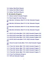
13.18. Front (L) Schematic Diagram
13.19. DV Jack Schematic Diagram
14. Printed Circuit Board
14.1. Power P.C.B.
14.2. Main P.C.B.
14.2.1. Main P.C.B. (1/4 Section)
14.2.2. Main P.C.B. (2/4 Section)
14.2.3. Main P.C.B. (3/4 Section)
14.2.4. Main P.C.B. (4/4 Section)
14.2.5. Main P.C.B. Address Information
14.3. Tuner P.C.B. and DV Jack P.C.B.
14.4. SD Card P.C.B. and Front (L) P.C.B.
15. Appendix for Schematic Diagram
15.1. Voltage and Waveform Chart
Note)
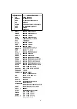
Circuit voltage and waveform described herein shall be regarded as reference information when
probing defect point, because it may differ from an actual measuring value due to difference of
Measuring instrument and its measuring condition and product itself.
15.1.1. Power P.C.B.
15.1.2. Main P.C.B.
15.1.3. Tuner P.C.B.
15.1.4. P59001 Connector
15.1.5. Waveform Chart
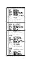
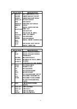
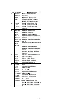
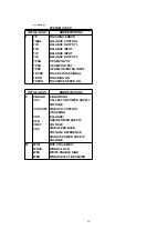
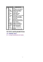
15.1.6. Abbreviations
51
Содержание DMR-EH55EC
Страница 7: ...3 2 Caution for DivX 4 Specifications 7 ...
Страница 8: ...8 ...
Страница 11: ...11 ...
Страница 12: ...12 ...
Страница 13: ...13 ...
Страница 17: ...5 Put deck upward and push out Tray by Eject Pin JZS0484 or minus screw driver small ...
Страница 48: ...10 7 DV Jack P C B 1 Remove 1 Screw A to remove DV Jack P C B 10 8 HDD 36 ...
Страница 49: ...1 Remove ATAPI Connector and HDD Power Connector 2 Remove 4 Screws A to remove HDD Angle with HDD 37 ...
Страница 55: ...11 1 2 Checking and Repairing of RAM Digital P C B Module 43 ...
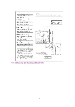
Страница 56: ...11 1 3 Checking and Repairing of Main P C B 44 ...
Страница 57: ...11 1 4 Checking and Repairing of HDD 45 ...
Страница 58: ...11 2 Caution for Replacing Parts 11 2 1 Items that should be done after replacing parts 46 ...
Страница 70: ...16 1 2 Packing Accessories Section 58 ...
Страница 78: ...66 ...
Страница 167: ...Ref No MODE E C B REC 3 8 1 2 3 1 PLAY 3 8 1 2 3 1 STOP 3 8 1 2 3 1 Q7802 ...


