33
9.1.3.
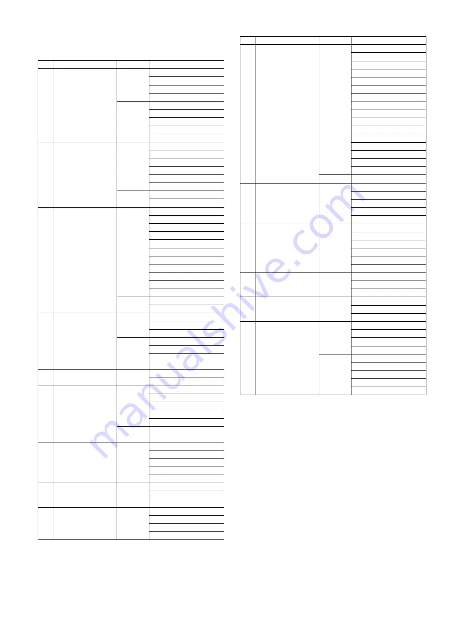
Disassembly Procedure
No.
Item
Fig
Removal
1
Rear Case Unit
2 Screws (A)
2 Screws (B)
2 Screws (C)
2 Screws (D)
FP9002(Flex)
FP9003(Flex)
FP9005(Flex)
FP9009(Flex)
Rear Case Unit
2
LCD Unit
1 Screw (E)
Grip Piece Rear
1 Screw (F)
3 Locking tabs
Rear Plate Unit
3 Locking tabs
Rear Plate Unit
LCD Unit
3
Main P.C.B.
FP3901(Flex)
FP3902(Flex)
FP3903(Flex)
FP3904(Flex)
FP9001(Flex)
FP9004(Flex)
FP9006(Flex)
FP9007(Flex)
FP9008(Flex)
3 Screws (G)
1 Hanging part
FP9010(Flex)
Main P.C.B.
4
Front Case /
Mount Box Unit
2 Screws (H)
2 Screws (I)
2 Screws (J)
2 Screws (K)
Jack Door
Front Case /
Mount Box Unit
5
Mount Box Unit
4 Screws (L)
Mount Box Unit
6
Flash Sub P.C.B.
(Fig. D10) 1 Screw (M)
1 Screw (N)
Tripod
Capacior Tape
Flash Sub P.C.B.
Method of wrapping the
capacitor tape
7
Top Case / Flash Unit
(Fig. D12) 2 Screws (O)
1 Screw (P)
Side Plate (R)
P8002(Connector)
Top Case / Flash Unit
8
Ex. LVF P.C.B.
(Fig. D13) 2 Screws (Q)
FP7902(Flex)
Ex. LVF P.C.B.
9
Flash Unit
Top Case Unit
(Fig. D14) 3 Screws (R)
Plate
Flash Unit
Top Case Unit
10
Top P.C.B.
(Fig. D15) 2 Screws (S)
FP8004(Flex)
Rear Dial SW Unit
FP8002(Flex)
FP8003(Flex)
MIC Cushion (C)
MIC Unit
MIC Cushion (B)
MIC Cushion (A)
Power Knob
Power LED Panel
iA Button
REC Button
Top Earth Plate
Top Plate (L)
Top P.C.B.
(Fig. D16) Note: (When installing)
11
AF LED P.C.B.
(Fig. D17) 1 Screw (T)
Rear OP Tape
2 Locking tabs
Flash Holder Piece
AF LED P.C.B.
12
Flash P.C.B.
(Fig. D18) P8502(Connector)
1 Screw (U)
1 Locking tab
Flash P.C.B. Cover
2 Solders
Flash P.C.B.
13
Speaker
(Fig. D19) 3 Locking tabs
Speaker FIX Plate
Speaker
14
Battery Door Unit
(Fig. D20) Battery Door Shaft
Battery Door Spring
Battery Door Unit
15
Heat Radiation Plate
Battery Case
(Fig. D21) 1 Screw (V)
Strap Holder (L)
7 Locking tabs
Heat Radiation Plate
(Fig. D22) Battery Lock Knob
Battery Lock Spring
Sheet
Battery out Spring
Battery Case
No.
Item
Fig
Removal
Содержание DMC-GF2CEB
Страница 3: ...3 11 3 General description Lens cleaning Interchangeable Lens H FS014042 53 ...
Страница 17: ...17 4 Specifications ...
Страница 23: ...23 7 Troubleshooting Guide 7 1 Checking Method of Body and Interchangeable Lens ...
Страница 24: ...24 ...
Страница 25: ...25 ...
Страница 26: ...26 ...
Страница 34: ...34 9 1 3 1 Removal of the Rear Case Unit Fig D1 ...
Страница 35: ...35 Fig D2 9 1 3 2 Removal of the LCD Unit Fig D3 ...
Страница 36: ...36 Fig D4 9 1 3 3 Removal of the Main P C B Fig D5 ...
Страница 37: ...37 Fig D6 9 1 3 4 Removal of the Front Case Mount Box Unit Fig D7 Fig D8 ...
Страница 38: ...38 9 1 3 5 Removal of the Mount Box Unit Fig D9 9 1 3 6 Removal of the Flash Sub P C B Fig D10 ...
Страница 39: ...39 Fig D11 9 1 3 7 Removal of the Top Case Flash Unit Fig D12 ...
Страница 41: ...41 Fig D16 9 1 3 11 Removal of the AF LED P C B Fig D17 9 1 3 12 Removal of the Flash P C B Fig D18 ...
Страница 47: ...47 Fig K1 ...


