37
9.3.
Disassembly Procedures
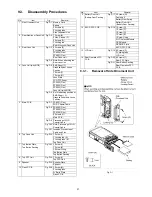
9.3.1.
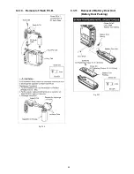
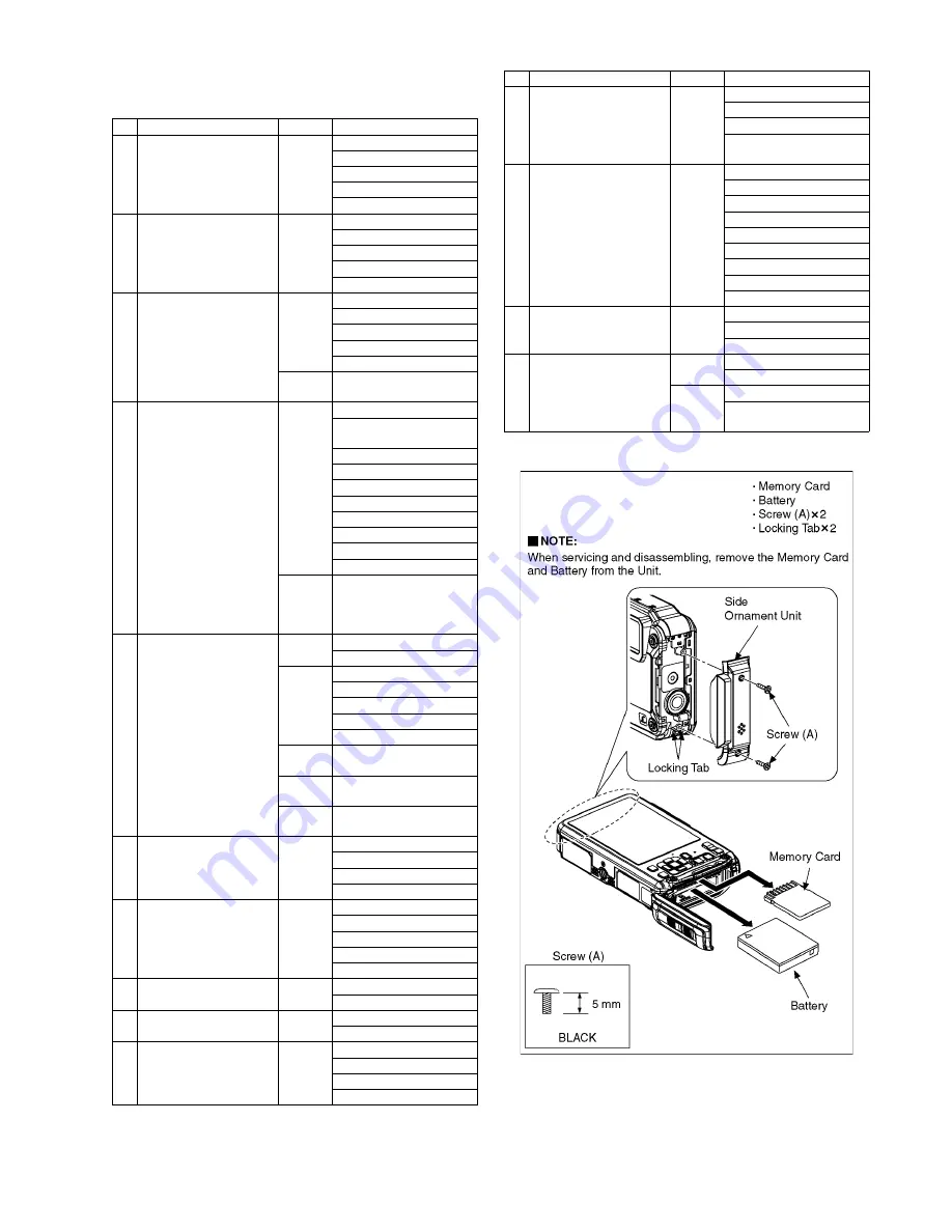
Removal of Side Ornament Unit
Fig. D1
No.
Item
Fig.
Removal
1
Side Ornament Unit
Fig. D1 Memory Card
Battery
2 Screws (A)
2 Locking tabs
Side Ornament Unit
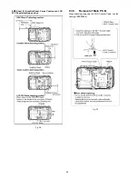
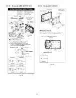
2
Rear Aluminum Case Unit
Fig. D2 1 Screw (B)
2 Hex. Screws (C)
2 Screws (D)
1 Locking tab
Rear Aluminum Case Unit
3
Rear Case Unit
Fig. D3 5 Screws (E)
2 Locking tabs
FP9004 (Flex)
FP9007 (Flex)
Rear Case Unit
Fig. D4 Note: When attaching the
Rear case Unit
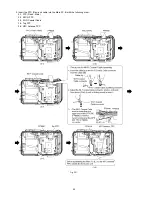
4
Lens Unit (with MOS)
Fig. D5 EMC Sheet (C)
Graphite Sheet, Venus
Cushion
1 Screw (F)
1 Screw (G)
Lens Plate
LCD FPC Sheet
FP9005 (Flex)
FP9002 (Flex)
FP9003 (Flex)
Lens Unit (with MOS)
Fig. D6 As for attaching position of
EMC Sheet ( C),
Graphite Sheet and Venus
Cushion.
5
Main P.C.B.
Fig. D7 FP9001 (Flex)
Wi-Fi Coaxial Cable
Fig. D8 FP9006 (Flex)
FP9008 (Flex)
FP9009 (Flex)
2 Screws (H)
Main P.C.B.
Fig. D9 Processing of Wi-Fi
Coaxial Cable
Fig. D10 Note: Processing of Wi-Fi
Coaxial Cable
Fig. D11 Insertion Procedures of
Cable and Flex
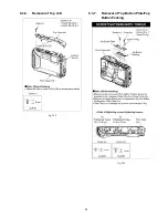
6
Top Case Unit
Fig. D12 1 Screw (I)
1 Locking tab (A)
2 Locking tabs (B)
Top Case Unit
7
Top Button Plate,
Top Button Packing
Fig. D13 1 Screw (J)
1 Screw (K)
1 Screw O-ring
Top Button Plate
Top Button Packing
8
Top FPC Unit
Fig. D14 1 Screw (L)
Top FPC Unit
9
Speaker
Fig. D15 Speaker Plate
Speaker
10 Flash P.C.B.
Fig. D16 1 Screw (M)
2 Locking tabs
FL Earth Plate
Flash P.C.B.
11 Battery Door Unit
(Battery Door Packing )
Fig. D17 2 Screws (N)
Door shaft
Battery Door Spring
Battery Door Unit
(Battery Door Packing)
12 MIC G FPC P.C.B.
Fig. D18 1 Screw (O)
1 Screw (P)
1 Screw (Q)
1 Screw (R)
1 Screw O-ring
Wi-Fi Antenna Module
GPS Module
GPS MIC Plate
MIC G FPC P.C.B.
13 LCD Unit
Fig. D19 2 Screws (S)
2 Locking tabs
LCD Unit
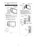
14 Rear Operation FPC
P.C.B.
Fig. D20 8 Screws (T)
Rear FPC Plate
Fig. D21 Rear Button Packing
Rear Operation FPC
P.C.B.
No.
Item
Fig.
Removal
Содержание DMC-FT5EA
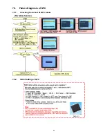
Страница 33: ...33 7 5 Failure Diagnosis of NFC 7 5 1 Checking flowchart of NFC failure 7 5 2 Initial Setting of NFC ...
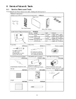
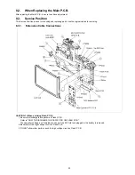
Страница 36: ...36 9 Disassembly and Assembly Instructions 9 1 Disassembly Flow Chart 9 2 P C B Location ...
Страница 38: ...38 9 3 2 Removal of Rear Aluminum Case Unit Fig D2 9 3 3 Removal of Rear Case Unit Fig D3 ...
Страница 43: ...43 9 3 6 Removal of Top Unit Fig D12 9 3 7 Removal of Top Button Plate Top Button Packing Fig D13 ...
Страница 44: ...44 9 3 8 Removal of Top FPC Unit Fig D14 9 3 9 Removal of Speaker Fig D15 ...
Страница 45: ...45 9 3 10 Removal of Flash P C B Fig D16 9 3 11 Removal of Battery Door Unit Battery Door Packing Fig D17 ...
Страница 46: ...46 9 3 12 Removal of MIC G FPC P C B Fig D18 9 3 13 Removal of LCD Unit Fig D19 ...
Страница 47: ...47 9 3 14 Removal of Rear Operation FPC P C B Fig D20 Fig D21 ...
Страница 56: ...56 ...


