10
CZ-RWSL2
Metal Panel
Installing the Operation Panel
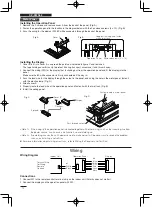
1 Remove the 2 screws and remove cover A from the back of the panel. (Fig. A)
2 Fasten the operation panel to the location in the diagram below with the 2 enclosed screws (4 × 10). (Fig. B)
3 Pass the wiring for the display (W2, 6P white connector) through the back of the panel.
Installing the Display
1 Cover B is fi t into Cover A, so spread the points as indicated in fi gure C and remove it.
The tape holding cover B is only to protect it during transport, so remove it and throw it away.
2 Connect the wiring (W2) for the display that is sticking out from the operation panel and fi t the display into the
panel.
Make sure the 6P white connector is fi rmly connected all the way in.
3 Pass the lead wire for the display through the cutout in the panel, and using the hole in the metal panel, fasten it
with the plastic clamp. (Fig. D)
4 Attach cover A.
5 Properly route the lead wire of the operation panel and fasten it with the twist lock. (Fig. B)
6 Install the ceiling panel.
<Note 1> If the wiring to the operation panel is bundled together with other wiring, such as the incoming line from
the power source, it can cause a malfunction, so avoid doing so.
<Note 2> If something causes the unit’s power source to make noise it will be necessary to resolve the problem,
such as by installing a noise fi lter.
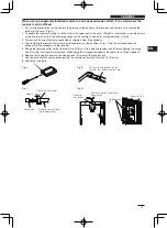
For more information about wiring or test runs, refer to Wiring the Receiver and Test Run.
Wiring
Wiring Diagram
Connections
1 Connect W1 to the remote control terminal strip on the indoor unit. (Polarity does not matter)
2 Connect the display and the operation panel with W2.
㨃㧝
㨃㧞
%0
%0
%0
White
Black
Blue
Yellow
Pink
Red
Gray
Black
Fig. A
Cover A
Fig. B
Loop extra wiring and fasten
with a twist lock.
Operation Panel
Enclosed screws (4 × 10)
Fig. C
Cover B
Connect
Spread
Display
Fasten to hole in metal panel
Pass through cutout
Display
Operation Panel
Indoor Unit
Terminal Strip
for Wiring
Remote
Controls
Fig. D


