INITIAL CENTER STATIC CONVERGENCE
Connect a dot/cross hatch generator to the receiver and tune in a signal. Observe
misconvergence at center of the screen only.
Adjust the R&B pole magnets; by separating tabs and rotating to converge blue with red.
Adjust the R&B and R&B&G pole magnets: by separating tabs and rotating to converge blue and
red (magenta) with green.
NOTE
Precise convergence at this point is not important.
PURITY ADJUSTMENT
When the receiver is in the serviceman mode for making electronic adjustments, press the
RECALL button on the remote control to enter purity check. (See the service adjustments
electronic controls procedure).
Operate the receiver for 60 minutes using the first purity check field (white screen) to stabilize
the CRT.
Fully degauss the receiver by using an external degaussing coil.
Press the RECALL button on the remote control again until the purity check (green screen)
appears.
Loosen the deflection yoke clamp screw and move the deflection yoke back as close to the purity
magnet as possible.
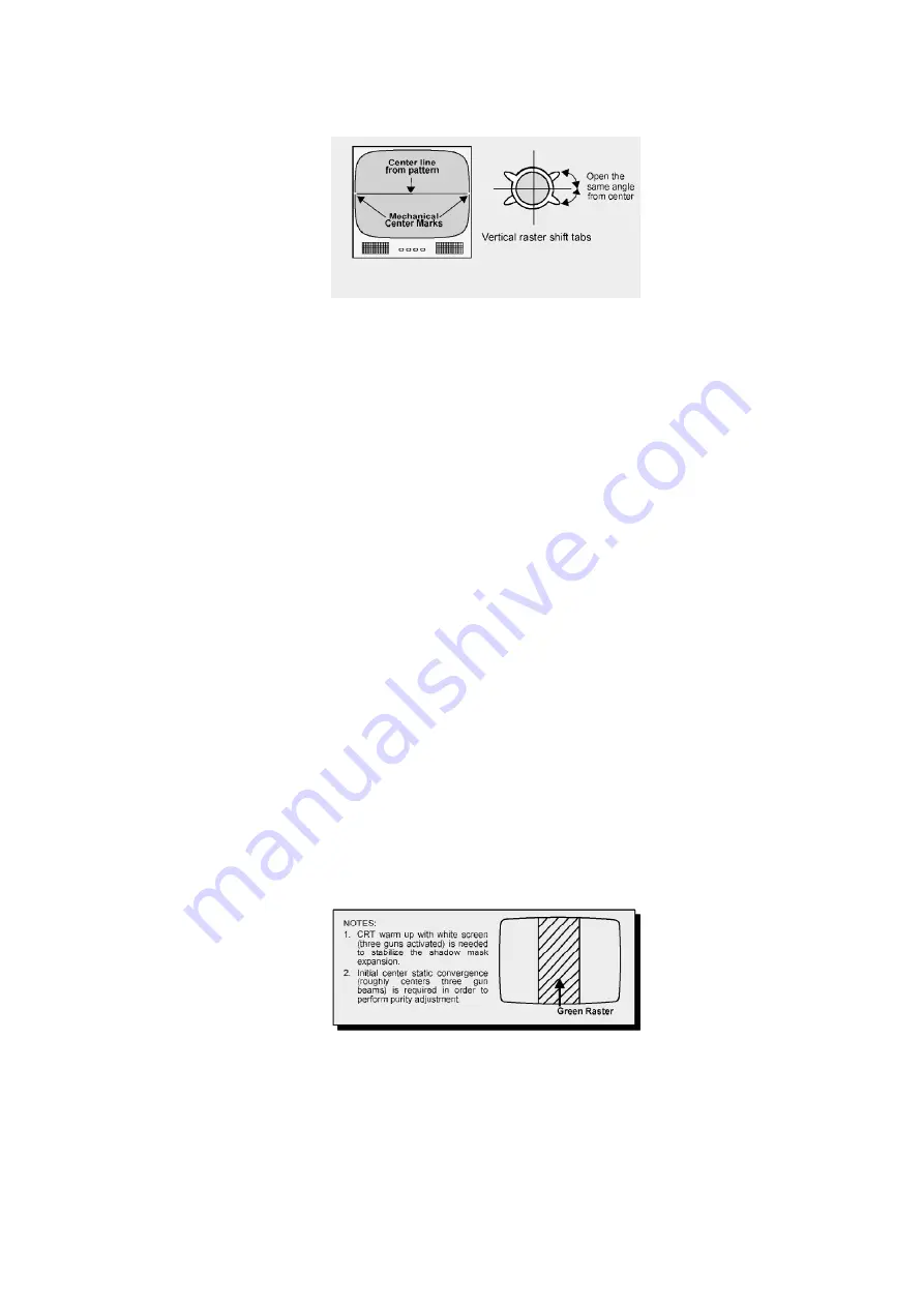
Adjust the purity rings to set the vertical green raster precisely at the center of the screen.
Green raster adjustment
Slowly move the deflection yoke forward until the best overall green screen is displayed.
Tighten the deflection yoke clamp screw.
Press the RECALL button on the remote control again until the purity check blue and red screens
appear and observe that good purity is obtained on each respective field.
Press the RECALL button on the remote control again until purity check (white screen) appears.
Observe the screen for uniform white. If purity has not been achieved, repeat the above
20
Содержание CT32E14J - 32" COLOR TV
Страница 33: ...13 1 1 C Board Chassis C Board component location 13 1 2 A Board Chassis 33 ...
Страница 34: ...13 1 3 A Board Surface mounted components A Board bottom view 34 ...
Страница 35: ...35 ...
Страница 37: ...37 ...
Страница 38: ...17 2 Notas de Esquematicos en Espa ñ ol 38 ...
Страница 39: ...39 ...
Страница 41: ...19 2 Parts List 41 ...
Страница 46: ...C2532 ECA1HM4R7B CAP E 4 7UF 50V 46 ...
Страница 49: ...IC3002 MM1501XNRE INT CKT 49 ...
Страница 83: ...12 3 Instructional flow chart for service mode continued 26 ...
Страница 95: ...Back Cover Removal CT 25L8G CT 25L8UG 38 ...
Страница 96: ...14 2 Chassis Components Rear view inside cabinet 39 ...
Страница 98: ...14 2 3 CT 20L8 A Board Chassis A Board Top view CT 20L8G 41 ...
Страница 99: ...14 2 4 CT 25L8 CT 25L8U A Board Chassis A Board Top view CT 25L8G CT 25L8UG 42 ...
Страница 100: ...14 2 5 A Board Surface mounted components A Board bottom view 43 ...
Страница 101: ...44 ...
Страница 103: ...46 ...
Страница 104: ...18 2 Notas de Esquemáticos en Español 47 ...
Страница 105: ...48 ...
Страница 107: ...20 2 Parts List 50 ...
Страница 113: ...D3019 CVS20A120MTA DIODE 56 ...
Страница 115: ...L805 EXCELDR35V FERRITE BEAD CT 20G8G CT 20G8SG CT 20L8G 58 ...
Страница 124: ...1 2 3 4 5 6 7 8 A B C D E F G H I J A BOARD 1 of 4 TNP2AH047AA AB CT 20L8G CT 20G8G CT 20G8SG ...
Страница 125: ...1 2 3 4 5 6 7 8 A B C D E F G H I J A BOARD 2 of 4 TNP2AH047AA AB CT 20L8 CT 20G8 CT 20G8S ...
Страница 126: ...1 2 3 4 5 6 7 8 A B C D E F G H I J A BOARD 3 of 4 TNP2AH047AA AB CT 20L8G CT 20G8G CT 20G8SG ...
Страница 127: ...1 2 3 4 5 6 7 8 A B C D E F G H I J A BOARD 4 of 4 TNP2AH047AA AB CT 20L8G CT 20G8G CT 20G8SG ...
Страница 128: ...1 2 3 4 5 6 7 8 A B C D E F G H I J A BOARD 1 of 4 TNP2AH047FA CT 25L8G CT 25L8UG ...
Страница 129: ...1 2 3 4 5 6 7 8 A B C D E F G H I J A BOARD 2 of 4 TNP2AH047FA CT 25L8G CT 25L8UG ...
Страница 130: ...1 2 3 4 5 6 7 8 A B C D E F G H I J A BOARD 3 of 4 TNP2AH047FA CT 25L8G CT 25L8UG ...
Страница 131: ...1 2 3 4 5 6 7 8 A B C D E F G H I J A BOARD 4 of 4 TNP2AH047FA CT 25L8G CT 25L8UG ...
Страница 133: ...1 2 3 4 5 6 7 8 A B C D E F G H I J C BOARD TNP2AA122FA AA CT 20L8G CT 20G8G CT 20G8SG CT 25L8G CT 25L8UG ...
Страница 134: ...1 2 3 4 5 6 7 8 A B C D E F G H I J A BOARD 1 of 2 TNP2AH047 CT 20L8G CT 20G8G CT 20G8SG CT 25L8G CT 25L8UG ...


