


NOTE
Screw configuration, type, and number of screws vary depending on the model of the receiver
serviced and the application; variou’s models are covered in this manual. Use same hardware
when reassembling the receiver.
- 3 screws at the top edge of the receiver (for 25” sets).
- 2 screws at the top edge of the receiver (for 20” sets).
- 1 screw by the A/V jacks.
- 1 screw at each lower corner of the receiver.
- 1 screw by the Flyback.
A-Board - Main chassis
1. Slide the chassis completely out of the guide rails.
2. Stand the receiver on its edge. The underside of the board is
completely accessible for component replacement.
Note:
Some tie-wraps that secure the wire dressings may need to be unfastened for chassis removal.
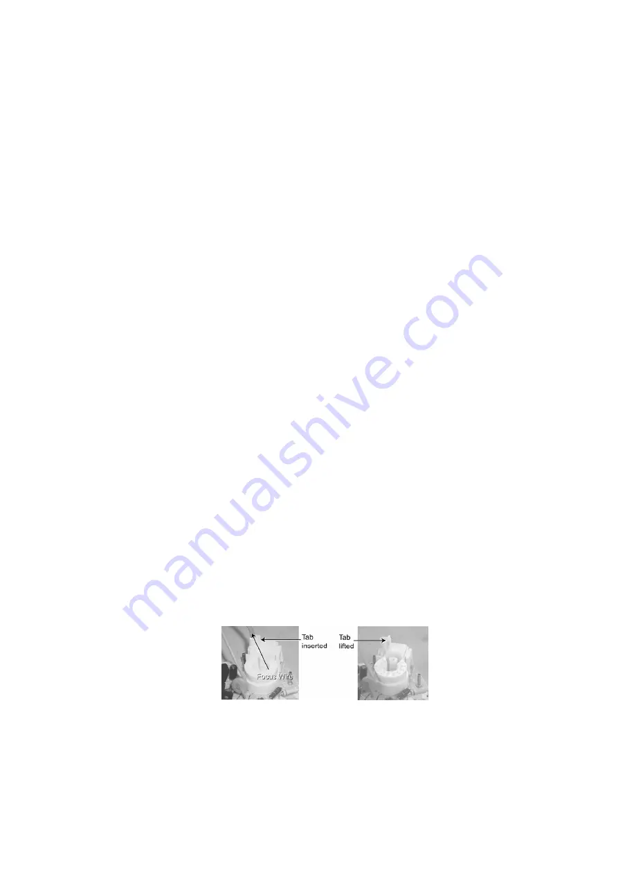
C-Board - CRT output
The board plugs onto the socket on the CRT neck. To release the Focus wire, use a dull object to
release the tab on the socket (near the wire opening) and carefully pull on the wire. To connect
the focus wire, press on the tab to lock it then insertthe wire in the opening and press on it until it
is fully inserted and locked in place.
Focus cable release
Speakers
Each speaker is secured to the cabinet with 4 screws.
14
Содержание CT32E14J - 32" COLOR TV
Страница 33: ...13 1 1 C Board Chassis C Board component location 13 1 2 A Board Chassis 33 ...
Страница 34: ...13 1 3 A Board Surface mounted components A Board bottom view 34 ...
Страница 35: ...35 ...
Страница 37: ...37 ...
Страница 38: ...17 2 Notas de Esquematicos en Espa ñ ol 38 ...
Страница 39: ...39 ...
Страница 41: ...19 2 Parts List 41 ...
Страница 46: ...C2532 ECA1HM4R7B CAP E 4 7UF 50V 46 ...
Страница 49: ...IC3002 MM1501XNRE INT CKT 49 ...
Страница 83: ...12 3 Instructional flow chart for service mode continued 26 ...
Страница 95: ...Back Cover Removal CT 25L8G CT 25L8UG 38 ...
Страница 96: ...14 2 Chassis Components Rear view inside cabinet 39 ...
Страница 98: ...14 2 3 CT 20L8 A Board Chassis A Board Top view CT 20L8G 41 ...
Страница 99: ...14 2 4 CT 25L8 CT 25L8U A Board Chassis A Board Top view CT 25L8G CT 25L8UG 42 ...
Страница 100: ...14 2 5 A Board Surface mounted components A Board bottom view 43 ...
Страница 101: ...44 ...
Страница 103: ...46 ...
Страница 104: ...18 2 Notas de Esquemáticos en Español 47 ...
Страница 105: ...48 ...
Страница 107: ...20 2 Parts List 50 ...
Страница 113: ...D3019 CVS20A120MTA DIODE 56 ...
Страница 115: ...L805 EXCELDR35V FERRITE BEAD CT 20G8G CT 20G8SG CT 20L8G 58 ...
Страница 124: ...1 2 3 4 5 6 7 8 A B C D E F G H I J A BOARD 1 of 4 TNP2AH047AA AB CT 20L8G CT 20G8G CT 20G8SG ...
Страница 125: ...1 2 3 4 5 6 7 8 A B C D E F G H I J A BOARD 2 of 4 TNP2AH047AA AB CT 20L8 CT 20G8 CT 20G8S ...
Страница 126: ...1 2 3 4 5 6 7 8 A B C D E F G H I J A BOARD 3 of 4 TNP2AH047AA AB CT 20L8G CT 20G8G CT 20G8SG ...
Страница 127: ...1 2 3 4 5 6 7 8 A B C D E F G H I J A BOARD 4 of 4 TNP2AH047AA AB CT 20L8G CT 20G8G CT 20G8SG ...
Страница 128: ...1 2 3 4 5 6 7 8 A B C D E F G H I J A BOARD 1 of 4 TNP2AH047FA CT 25L8G CT 25L8UG ...
Страница 129: ...1 2 3 4 5 6 7 8 A B C D E F G H I J A BOARD 2 of 4 TNP2AH047FA CT 25L8G CT 25L8UG ...
Страница 130: ...1 2 3 4 5 6 7 8 A B C D E F G H I J A BOARD 3 of 4 TNP2AH047FA CT 25L8G CT 25L8UG ...
Страница 131: ...1 2 3 4 5 6 7 8 A B C D E F G H I J A BOARD 4 of 4 TNP2AH047FA CT 25L8G CT 25L8UG ...
Страница 133: ...1 2 3 4 5 6 7 8 A B C D E F G H I J C BOARD TNP2AA122FA AA CT 20L8G CT 20G8G CT 20G8SG CT 25L8G CT 25L8UG ...
Страница 134: ...1 2 3 4 5 6 7 8 A B C D E F G H I J A BOARD 1 of 2 TNP2AH047 CT 20L8G CT 20G8G CT 20G8SG CT 25L8G CT 25L8UG ...


