


37
12.11. Patrol Operation
A. Purpose
To monitor air dirtiness level by using Patrol sensor and to maintain air freshness by activates e-ion operation.
B. Control Condition
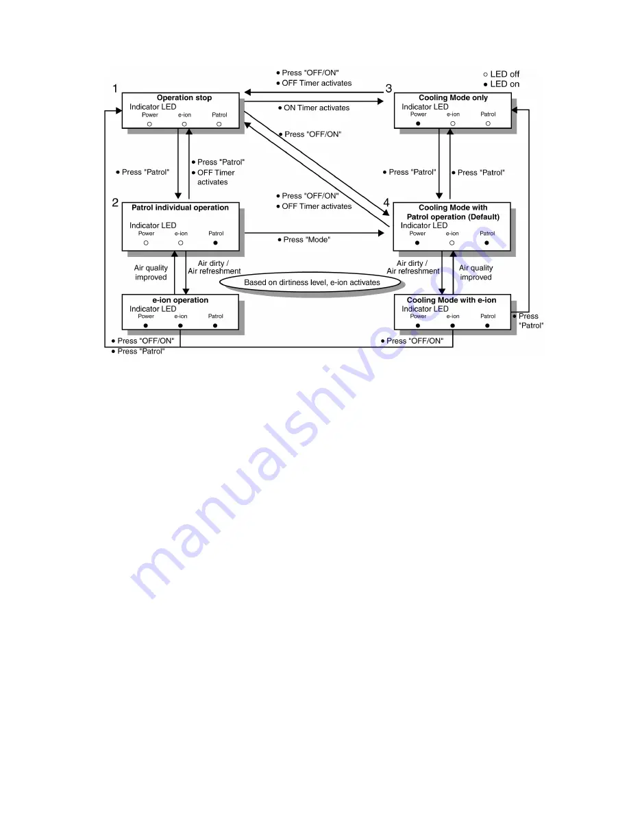
a. Patrol operation start condition
• When the unit operation is started with “OFF/ON” button.
• When the unit stops, “Patrol” button is pressed, Patrol individual operation will start.
• During cooling only operation, “Patrol” button is pressed.
b. Patrol operation stop condition
When any of the following condition is fulfilled:
• When “OFF/ON” button is pressed.
• During any operation with Patrol, “Patrol” button is pressed again.
• When “e-ion” button is pressed.
• When OFF Timer activates.
c. Patrol operation disable
• To disable the Patrol Operation during unit start (default) with “OFF/ON” button, press “Patrol” button and hold for 5 seconds,
then release.
• To disable the Patrol Operation, press “Patrol” button and hold for 15 seconds, then release.
C. Control Content
a. Patrol Sensor Control
• First 2 minutes from Patrol function activates is stabilization time, during stabilization time, no air dirtiness level is monitored.
The Air Dirtiness level is set to level 2.
• After that, gas sensor starts to record the resistance value at fixed interval. Higher resistance value indicates cleaner air.
• The air dirtiness level is monitored by comparing the current resistance value with maximum resistance value from time to time
to get the Air Dirtiness Value.
• There are 3 air dirtiness levels, based on the Air Dirtiness Value:
- Air Dirtiness level 0: Clean
- Air Dirtiness level 1: Moderate
- Air Dirtiness level 2: Contaminated
Содержание CS-NE9LKE
Страница 12: ...12 4 Location of Controls and Components 4 1 Indoor Unit 4 2 Outdoor Unit 4 3 Remote Control...
Страница 13: ...13 5 Dimensions 5 1 Indoor Unit...
Страница 14: ...14 5 2 Outdoor Unit...
Страница 15: ...15 6 Refrigeration Cycle Diagram...
Страница 16: ...16 7 Block Diagram...
Страница 17: ...17 8 Wiring Connection Diagram 8 1 Indoor Unit...
Страница 18: ...18 8 2 Outdoor Unit...
Страница 19: ...19 9 Electronic Circuit Diagram 9 1 Indoor Unit...
Страница 20: ...20 9 2 Outdoor Unit...
Страница 21: ...21 10 Printed Circuit Board 10 1 Indoor Unit 10 1 1 Main Printed Circuit Board...
Страница 22: ...22 10 1 2 Power Printed Circuit Board 10 1 3 Indicator Printed Circuit Board...
Страница 23: ...23 10 1 4 Receiver Printed Circuit Board 10 1 5 High Voltage Power Supply Printed Circuit Board...
Страница 24: ...24 10 2 Outdoor Unit...
Страница 80: ...80 16 1 3 To remove discharge grille...
Страница 81: ...81 16 1 4 To remove control board 16 1 5 To remove cross flow fan and indoor fan motor...
Страница 82: ...82...
Страница 84: ...84 17 Technical Data 17 1 Operation Characteristics 17 1 1 CU NE9LKE...
Страница 85: ...85...
Страница 86: ...86...
Страница 87: ...87...
Страница 88: ...88 17 1 2 CU NE12LKE...
Страница 89: ...89...
Страница 90: ...90...
Страница 91: ...91...


