


3. Fully open the handle Lo of the manifold gauge, turn on the power of the vacuum pump and continue the vacuum process for
at least one hour.
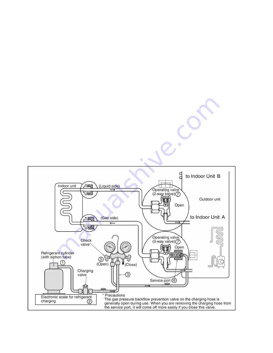
4. Confirm that the low pressure gauge shows a reading of -0.1 Mpa (-76 cmHg), then fully close the handle Lo, and turn off the
vacuum pump. Wait for 1-2 minutes, then check to make sure that the needle of the Low pressure gauge has not returned. See
Fig. 13 for the remaining steps of this procedure.
5. Set the refrigerant cylinder onto the electronic scale, then connect the hose the cylinder and to the connection port for the
electronic scale. (1)(2)
Precaution:
Be sure to set up the cylinder for liquid charging. If you use a cylinder equipped with a siphon tube, you can charge the liquid
without having to turn the cylinder around.
6. Remove the charging hose of the manifold gauge from the vacuum pump adaptor, and connect it to the connection port of the
electronic scale. (2)(3)
7. Open the valve of the refrigerant cylinder, then open the charging valve slightly and close it. Next, press the check valve of the
manifold gauge and purge the air. (2)(4) (Watch the liquid refrigerant closely at this point.)
8. After adjusting the electronic scale to zero, open the charging valve, then open the valve Lo of the manifold gauge and charge
with the liquid refrigerant. (2)(5) (Be sure to read the operating instructions for the electronic scale.)
9. If you cannot charge the stipulated amount, operate the unit in the cooling mode while charging a little of the liquid at a time
(about 150 g/time as a guideline). If the charging amount is insufficient from one operation, wait about one minute, then use the
same procedure to do the liquid charging again.
Precaution:
Never use the gas side to allow a larger amount of liquid refrigerant to be charged while operating the unit.
10. Close the charging valve, and after charging the liquid refrigerant inside the charging hose, fully close the valve Lo of the
manifold gauge, and stop the operation of the unit. (2)(5)
11. Quickly remove the charging hose from the service port. (6) If you stop midway through, the refrigerant that is in the cycle will
be discharged.
12. After putting on the caps for the service port and operating valve, inspect around the caps for a gas leak. (6)(7)
Fig. 13 Re-charging refrigerant
72
Содержание CS-F14DD3E5
Страница 8: ...4 DIMENSIONS 4 1 CS F14DD3E5 CS F18DD3E5 8 ...
Страница 9: ...4 2 CU B14DBE5 CU B18DBE5 9 ...
Страница 10: ...5 REFRIGERATION CYCLE 5 1 CS F14DD3E5 CU B14DBE5 CS F18DD3E5 CU B18DBE5 10 ...
Страница 11: ...6 BLOCK DIAGRAM 6 1 CS F14DD3E5 CS F18DD3E5 6 2 CU B14DBE5 11 ...
Страница 12: ...6 3 CU B18DBE5 12 ...
Страница 13: ...7 WIRING DIAGRAM 7 1 CS F14DD3E5 CS F18DD3E5 13 ...
Страница 14: ...7 2 CU B14DBE5 14 ...
Страница 15: ...7 3 CU B18DBE5 15 ...
Страница 17: ...8 2 Remote control display 17 ...
Страница 18: ...8 3 Remote control panel 18 ...
Страница 85: ...13 TECHNICAL DATA 13 1 Sound data 85 ...
Страница 86: ...86 ...
Страница 87: ...13 2 Sound measurement point 13 2 1 Indoor unit 13 2 2 Outdoor unit 87 ...
Страница 88: ...13 3 Discharge and suction pressure 13 3 1 Saturation temperature of discharge and suction pressure COOLING 88 ...
Страница 89: ...HEATING 89 ...
Страница 91: ...91 ...
Страница 93: ...93 ...
Страница 95: ...13 5 Fan performance 13 5 1 CS F14DD3E5 Fan performance test report Fan performance curve 95 ...
Страница 96: ...13 5 2 CS F18DD3E5 Fan performance test report Fan performance curve 96 ...
Страница 98: ...13 7 Operating characteristics S C Starting Current R C Running Current IPT Power Consumption 98 ...
Страница 99: ...14 REPLACEMENT PARTS 14 1 Indoor unit CS F14DD3E5 CS F18DD3E5 99 ...
Страница 101: ...14 2 Outdoor unit CU B14DBE5 CU B18DBE5 101 ...
Страница 102: ...CU B14DBE5 CU B18DBE5 102 ...
Страница 104: ...15 PRINT PATTERN 15 1 Indoor unit INDOOR UNIT PRINTED CIRCUIT BOARD MAIN 104 ...
Страница 105: ...15 2 Outdoor unit OUTDOOR UNIT PRINTED CIRCUIT BOARD MAIN 105 PHAAM Printed in Malaysia SFYW0605 01 ...


