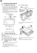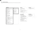
6.2. Assembly Flow Chart
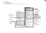
The following chart is the procedure for assembling the casing and inside parts for internal inspection when carrying out the servicing.
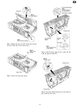
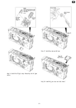
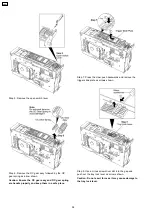
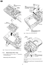
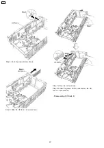
7.2.2 Disc Trays
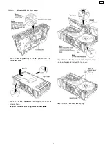
Step 1: Tilt and fix the 5 disc trays.
Step 2: Push the 5 disc trays until it stop.
Step 3: Push the tray drive rack until it stop.
Step 4: Fix the lock lever 1 onto the pitch plate.
Step 7: Install the UD connection lever.
Step 5: Press and hold the claw at the pitch plate then push
the UD rack R.
Step 6: Push the claw and slide the UD rack L.
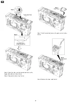
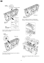
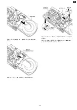
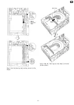
7.2.3 UD Base Assembly
Step 1: Push the traverse slide plate.
Step 2: Install the UD base assembly.
Step 3: Turn UD connection lever anti-clockwise,
the UD base assembly will move downwards.
Step 4: Install the tray lock lever to the mechanism base
and push the tray lock lever with a hand to fix it.
Step 5: Push the disc trays back to the unit.
Lock lever 1
UD connection lever
Trigger Slide Plate
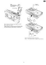
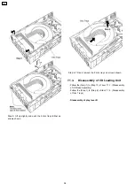
7.2.5 Traverse Unit
Step 1: Turn over the unit and install traverse unit.
Step 2: Push the traverse slide plate to lock the
traverse unit.
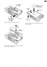
Step 1: Install the plunger assembly.
Step 3: The claw should be latched.
Step 2: Install the CD Loading P.C.B.
Step 5: Solder the 4 points.
7.2.4 CD Loading P.C.B
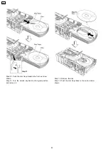
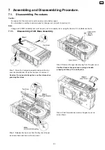
7.2.1 CD Loading Unit
Step 1: Turn over the unit and install the plunger lever in 90
degree position.
Step 2: Push in the plunger lever.
Plunger lever
Plunger assembly
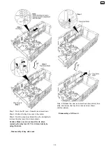
Step 16: Install the cam gear.Make sure the big hole is fix at the
position (A) at 90 degree.
Step 17: Turn the cam gear anti-clockwise until the big hole
stop at position (B).
Step 18: Install the relay gear 1, relay gear 3, UD gear 2, long
gear and play gear 2 respectively.
Step 19: Install the tray relay gear.
Step 20: Install the pulley gear followed by the belt.
Step 21: Install the change spring.
Step 23: Install the pitch plate.
Step 24: The 4 claws should be latched properly.
Step 9: Install the play switch lever.
Step 10: Fix the spring below the rib.
Step 11: Install the the function lever.
Step 12: Install the play gear 1.
Function lever
Play gear 1
Function gear and main drive gear
Step 13: Install the main drive gear.
Step 14: Install the function gear.
Gears
Step 15: Install the relay gear 2, switching gear and UD gear 1
respectively.
Pulley gear and belt
Change spring
Pitch plate
Step 25: Fix it with 3 screws.
Trigger gear
Step 26: Install the trigger gear in sequence.
Step 27: Use the screwdriver to turn the hole
on the UD gear 2 align with the pitch
plate hole.
UD rack R
Step 28: Insert the UD rack R.
Step 29: Push the UD rack R.
Step 30: Insert the UD rack L.
Step 31: Push the claw.
UD rack L
Step 32: Pull the UD rack L.
Tray drive rack
Step 33: Install the tray drive rack.
Play lever B
Step 34: Install the play lever B below the rib.
Step 3: Turn over the unit and install the motor unit properly.
Play switch lever
Step 5: Install the CD Loading P.C.B.
Step 6: The claws should be latched.
Step 4: Install the plunger assembly.
CD loading P.C.B.
Step 7: Solder the 4 points.
Step 8: Fix it with 4 screws.
Step 22: Install the lock lever 2 in sequence.
Step 6: Install the trigger slide plate, push forwards and
push the trigger until locked by the claw.
Step 7: Install the OC gear spring followed by the OC gear
assy.
Step 8: Install the open switch lever.
Step 9: Install the gear cover.
Step 11: Install the top cover, fix the top cover hook to
the tray rear stopper.
Step 12: Fixed the top cover, the 2 claws should be latched.
Step 10: Install the open lever spring.
Step 4: Fix it with 4 screws.
CRS1
50
Содержание CRS1
Страница 3: ...1 Mechanism Overview 3 CRS1 ...
Страница 14: ... As the plunger only activate at 2 position of cam gear The plunger mode summary as below 14 CRS1 ...
Страница 28: ... For tray 1 selection flow chart below will be used 28 CRS1 ...
Страница 48: ...48 CRS1 ...
Страница 52: ...CRS1 52 ...
Страница 97: ...12 Exploded Views 12 1 CD Loading Mechanism 97 CRS1 ...
Страница 98: ...98 CRS1 ...
Страница 99: ...99 CRS1 ...

