background image


33 


Figure 2-23 


2.8


Network  

Here is for you to input network information. 

The single network adapter interface is shown as in Figure 2-24. 


MTU: It is to set MTU value of the network adapter. The value ranges from 1280-7200 bytes. 

The default setup is 1500 bytes. Please note MTU modification may result in network 

adapter reboot and network becomes off. That is to say, MTU modification can affect current 

network service. System may pop up dialog box for you to confirm setup when you want to 

change MTU setup. Click OK button to confirm current reboot, or you can click Cancel button 

to terminate current modification. Before the modification, you can check the MTU of the 

gateway; the MTU of the DVR shall be the same as or is lower than the MTU of the gateway . 

In this way, you can reduce packets and enhance network transmission efficiency. 

Right 

now, the value here is for read-only. 

The following MTU value is for reference only.  

  1500: Ethernet information packet max value and it is also the default value. It  is the 

typical setup when there is no PPPoE or VPN. It is the default setup of some router, 

switch or the network adapter.  

  1492: Recommend value for PPPoE. 

  1468: Recommend value for DHCP. 


LAN download: System can process the downloaded data first if you enable this function. 

The download speed is 1.5X or 2.0X of the normal speed. 


IP Version: There are two options: IPv4 and IPv6. Right now, system supports these two IP 

address format and you can access via them.  

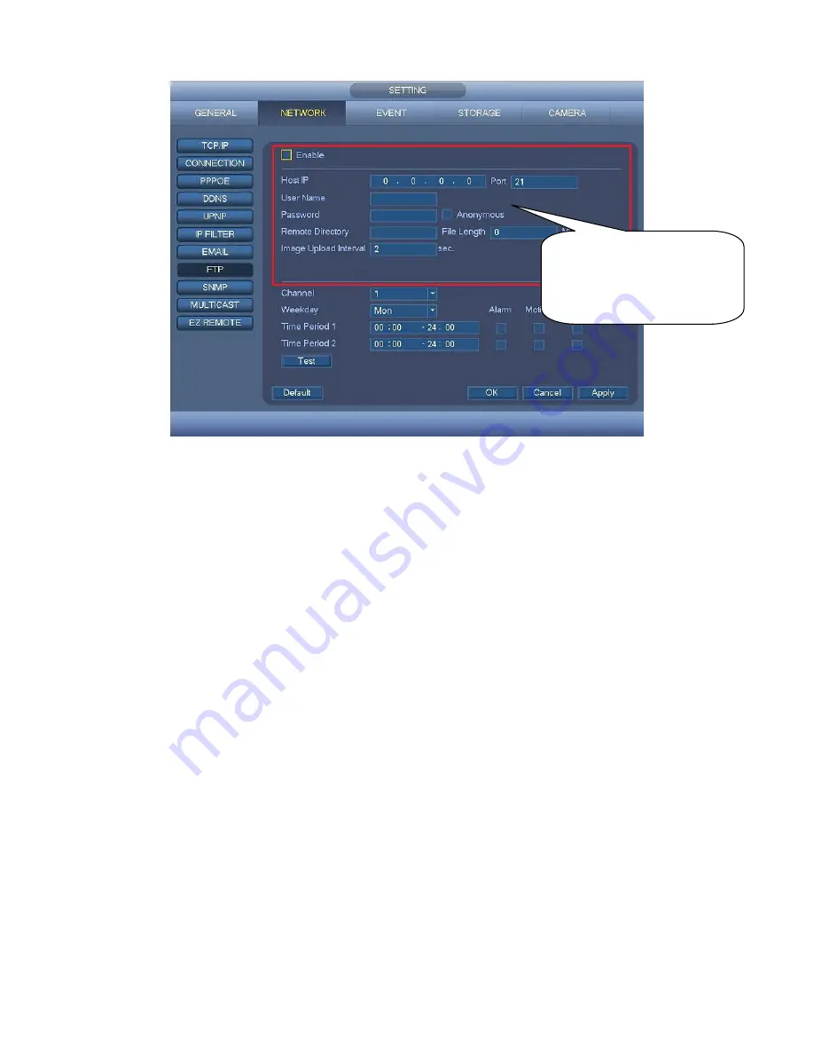
Please input the 

corresponding information 

here, if you just upload the 

image FTP. 

Содержание CJ-HDR216

Страница 1: ...HD Analog Recorder Quick Start Guide Model No CJ HDR216 CJ HDR416 Version 1 0 0...

Страница 2: ...16 3 1 7 Rear Panel 6 1 8 Connection Sample 9 1 9 Alarm Input and Output Connection 10 1 9 1 Alarm Input and Output Details 11 1 9 2 Alarm Input Port 11 1 9 3 Alarm Output Port 12 2 Overview of Naviga...

Страница 3: ...edundancy 28 2 7 Snapshot 29 2 7 1 Schedule Snapshot 29 2 7 2 Trigger Snapshot 30 2 7 3 Priority 32 2 7 4 Image FTP 32 2 8 Network 33 2 9 Pan Tilt Zoom 34 2 9 1 Pan Tilt Zoom Setup 35 2 9 2 Pan Tilt Z...

Страница 4: ...on Keep upwards Handle with care Do not apply power to the DVR before completing installation Do not place objects on the DVR 4 Qualified engineers needed All the examination and repair work should be...

Страница 5: ...uded in the accessory bag 1 2 About Front Panel and Rear Panel For detailed information of the function keys in the front panel and the ports in the rear panel please refer to the User s Manual includ...

Страница 6: ...her 1 Loosen the screws of the upper cover 2 Line up the HDD to the four holes of the HDD bracket 3 Use four screws to fix HDD 4 Unfasten the HDD power cable 5 Use the special data cable to connect th...

Страница 7: ...rt Connect to USB2 0 storage device mouse and etc Up 1 Down 4 Activate current controls and then move up move down or jump Change setup increase decrease numeral Assistant function such as PTZ menu Sw...

Страница 8: ...vious character before the cursor In HDD information interface click to switch HDD record time and other information Realize other special functions Shift SHIFT In textbox click it to switch between n...

Страница 9: ...ght becomes on when system is recording Remote Control Receiver Window IR It is to retrieve the signal from the remote control Cancel Esc Go to previous menu or cancel current operation Close the top...

Страница 10: ...to view analog video output 3 AUDIO IN Audio input port Connect to audio input device such as speaker 4 VIDEO IN Video input port Connect to analog camera video input signal 5 Power input port Input...

Страница 11: ...or transfer transparent COM data 3 1 16 Alarm input port 1 16 There are four groups The first group is from port 1 to port 4 the second group is from port 5 to port 8 the third group is from 9 to 12 a...

Страница 12: ...nput wire CTRL 12V Control power output Controller 12V power output It is to control the on off alarm relay output 4 VIDEO OUT Video output port Connect to video output devices such as TV 5 AUDIO OUT...

Страница 13: ...h definition audio and video signal output port It transmits uncompressed high definition video and multiple channel data to the HDMI port of the display device 13 eSATA eSATA port External SATA port...

Страница 14: ...10 Figure 1 5 CJ HDR416 The connection sample is shown as below See Figure 1 6 Figure 1 6 1 9 Alarm Input and Output Connection Important...

Страница 15: ...Alarm output public end NC Normal close alarm output port CTRL 12V Control power output For external alarm you need to close the device power to cancel the alarm Voltage current 500mA 12V Rated curre...

Страница 16: ...rt T T output wire R R input wire Relay Specification Model JRC 27F Material of the touch Silver Rating Resistance Load Rated switch capacity 30VDC 2A 125VAC 1A Maximum switch power 125VA 160W Maximum...

Страница 17: ...ou see corresponding dialogue box System is shutting down Do not click power on off button directly Do not unplug the power cable or click power on off button to shut down device directly when device...

Страница 18: ...2 1 The system login interface is shown as in Figure 2 2 System consists of two accounts Username ADMIN Password 12345 administrator local and network Username default Password default hidden user You...

Страница 19: ...control function has the following features Support preview playback In the preview desktop system can playback previous 5 60 minutes record of current channel Please go to the Main Menu Setting Gene...

Страница 20: ...ording Click it again system stops recoridng You can find the record file on the flash disk 4 Snap Click to snapshot once The snapshot file is saved on the USB device or HDD You can go to the Playback...

Страница 21: ...Operation System supports main stream and sub stream There are three statuses auto manual off Please highlight icon to select corresponding channel Manual The highest priority After manual setup all...

Страница 22: ...function 2 5 Search Playback Click Playback button in the main menu or right click mouse and then select Playback when you are previewing search interface is shown as below See Figure 2 6 Usually ther...

Страница 23: ...l option 3 Calendar The blue highlighted date means there is picture or file Otherwise there is no picture or file In any play mode click the date you want to see you can see the corresponding record...

Страница 24: ...d file Click the button to view the locked file Return Click button system goes back to the calendar and channel setup interface Please note For the file that is writing or overwriting it cannot be lo...

Страница 25: ...cord The time bar is beginning with 0 o clock when you are setting the configuration The time bar zooms in the period of the current playback time when you are playing the file 11 Backup Select the fi...

Страница 26: ...umber button system can switch to the same period of the corresponding channel to play 16 Digital zoom When the system is in full screen playback mode left click the mouse in the screen Drag your mous...

Страница 27: ...rner to playback records by time See image on the left side of the Figure 2 8 For example input time 11 00 00 and then click Search button you can view all the record files after 11 00 00 The records...

Страница 28: ...video information Add Mark When system is playback click Bookmark button you can go to the following interface See Figure 2 9 Figure 2 9 Playback Mark During 1 window playback mode click mark file li...

Страница 29: ...em Note After you go to the mark management interface system needs to pause current playback System resumes playback after you exit mark management interface If the mark file you want to playback has...

Страница 30: ...cord System can pre record the video before the event occurs into the file The value ranges from 1 to 30 seconds depending on the bit stream Redundancy System supports redundancy backup function You c...

Страница 31: ...us menu There are color bars for your reference Green color stands for regular recording yellow color stands for motion detection and red color stands for alarm recording The blue means the MD and ala...

Страница 32: ...16 2 6 2 Redundancy Redundancy function allows you to memorize record file in several disks When there is file damage occurred in one disk there is a spare one in the other disk You can use this func...

Страница 33: ...write disk Main menu Setting Storage HDD Manage System needs to reboot to get setup activated Now you can search or playback file in redundant disk Dismantle the disk and play it in another PC 2 7 Sna...

Страница 34: ...low to enable the activation snapshot function After you enabled this function system can snapshot when the corresponding alarm occurred In main menu from Setting Camera Encode Snapshot interface here...

Страница 35: ...Setting Event Detect please enable snapshot function for specified channels Figure 2 21 Or In main menu from Setting Event Alarm Figure 2 22 please enable snapshot function for specified channels Fig...

Страница 36: ...larm occurs and otherwise system just operates the schedule snapshot 2 7 4 Image FTP In the main menu from Setting Network FTP you can set FTP server information Please enable FTP function and then cl...

Страница 37: ...teway the MTU of the DVR shall be the same as or is lower than the MTU of the gateway In this way you can reduce packets and enhance network transmission efficiency Right now the value here is for rea...

Страница 38: ...nformation Besides when PPPoE is operating you cannot modify IP Subnet mask Gateway Default gateway Here you can input the default gateway Please note system needs to check the validity of all IPv6 ad...

Страница 39: ...items Please select channel first See Figure 2 25 Protocol Select corresponding PTZ protocol Address Input corresponding PTZ address Baud rate Select baud rate Data bit Select data bit Default value i...

Страница 40: ...e 2 27 In Figure 2 27 please click direction arrows See Figure 2 28 to adjust PTZ position There are total 8 direction arrows Please note if you use remote control you can use just four directions Up...

Страница 41: ...such as Safari fire fox browser Google browser Device supports multiple channel monitor PTZ control DVR parameter setup on the Apple PC 3 2 Login Open IE and input DVR address in the address column Fo...

Страница 42: ...e LAN mode after you logged in you can see the main window See Figure 3 3 Click the channel name on the left side you can view the real time video Figure 3 3 3 3 2 WAN Login In WAN mode after you logg...

Страница 43: ...for electronic version of the User s Manual Slight difference may be found in user interface All the designs and software here are subject to change without prior written notice All trademarks and re...

Отзывы: