


Operation
3
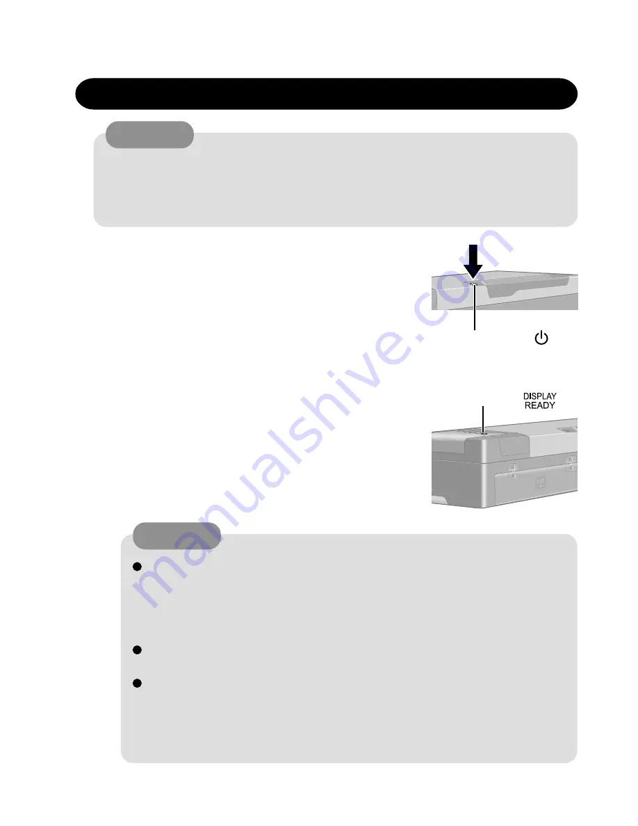
Starting Up/Shutting Down
1
Turn on your computer
Press the power switch and hold it for approximately
one second until the power indicator turns on before
releasing it.
Starting Up
2
After confirming the display status in-
dicator lit, turn on the wireless
display
After confirming that the power indicator has turned on, avoid the following
until Windows has completed loading.
• Connecting or disconnecting the AC adaptor.
• Touching the power switch.
• Performing any keyboard or external mouse operations.
Once the computer is powered off, you must wait at least ten seconds before
powering it on again.
When the CPU temperature rises, the computer may not power on to prevent
the CPU from overheating. Should this happen, allow the computer to cool
down then switch the power on again.
If the computer still does not power on, contact Panasonic Technical Sup-
port.
CAUTION
Do not maximize the MS-DOS screen. Once maximized, the connection with the
wireless display is interrupted. The connection cannot be re-established and the
computer no longer operates. In such cases, the computer must be powered off.
Data may be lost.
CAUTION
Power Switch
Display Status
Indicator
6-1
Содержание CF-07 Series
Страница 3: ... RU 8 6 1 2 2 ...
Страница 4: ...2 3 ...
Страница 21: ...9 6 System Memory Map ...
Страница 24: ...8 Diagnosis Procedure Basic Procedures 11 ...
Страница 41: ...Example ALT F brings up the File menu Input screen Order of test flow selection 16 5 ...
Страница 43: ...14 Wiring Connection Diagram 17 ...
Страница 47: ...16 Exploded View 1 Exploded View 1 2 19 1 ...
Страница 48: ...2 Exploded View 2 2 19 2 ...
Страница 64: ......
Страница 65: ......
Страница 66: ......
Страница 67: ......
Страница 68: ......
Страница 69: ......
Страница 70: ...CF 07LZ5ZYXM 1 Schematic Diagrams Upper Main 1 CPU 1 2 ...
Страница 71: ...Upper Main 2 CPU 2 2 2 ...
Страница 72: ...U s 3 pper Main 3 Resister ...
Страница 73: ...U k 4 pper Main 4 Cloc ...
Страница 74: ...U 5 pper Main 5 GMCH M 1 2 ...
Страница 75: ...pper Main 6 GMCH M 2 2 U U 6 ...
Страница 76: ...pper Main 7 ON Board Memory 7 U U ...
Страница 77: ...pper Main 8 Micro DIMM 8 U U ...
Страница 78: ...Upper Main 9 iCH2 M 1 2 9 ...
Страница 79: ...Upper Main 10 iCH2 M 2 2 10 U U ...
Страница 80: ...pper Main 11 Terminator 11 U U ...
Страница 81: ...U Upper Main 12 HDD 12 ...
Страница 82: ...Upper Main 13 BIOS 13 U U ...
Страница 83: ...Upper Main 14 PCMCIA Controller 14 ...
Страница 84: ...pper Main 15 Slot 1 WLSD Connector 15 U U ...
Страница 85: ...pper Main 16 LED Connector 16 U ...
Страница 86: ...Upper Main 17 Base Connector 17 ...
Страница 87: ...Upper Main 18 VCPUCORE VC25 18 ...
Страница 88: ...pper Main 19 Power Circuit 19 U U ...
Страница 89: ...Upper Main 20 Modem Controller 20 ...
Страница 90: ...pper Main 21 Line Codec 21 U U ...
Страница 91: ...Lower Main 1 Connector 22 L L ...
Страница 92: ...ower Main 2 Super I O 23 L ...
Страница 93: ...Lower Main 3 COM Connector 24 L L ...
Страница 94: ...Lower Main 4 Wireless Connector 25 L L ...
Страница 95: ...Lower Main 5 KBC 26 L L ...
Страница 96: ...Lower Main 6 Q AW for Doc 27 L L ...
Страница 97: ...Lower Main 7 Doc Connector 28 ...
Страница 98: ...Lower Main 8 EC 29 ...
Страница 99: ...L LLower Main 9 Reset 30 ...
Страница 100: ...L Lower Main 10 DC IN 31 ...
Страница 101: ...L Lower Main 11 VD3 VD5 32 ...
Страница 102: ...L Lower Main 12 Power Circuit2 33 ...
Страница 103: ...L Lower Main 13 BATT SW 34 ...
Страница 104: ...Lower Main 14 RF DC DC 35 ...
Страница 105: ...Lower Main 15 Charger 36 ...
Страница 106: ...Lower Main 16 Doc Power 37 ...
Страница 107: ...Lower Main 17 VD18 38 ...
Страница 108: ...Serial Connector 39 S S ...
Страница 109: ...D U Sub Connector 40 D DDD ...
Страница 110: ...D U Docking Connector 41 D DD ...
Страница 111: ...D U Sub Connector 42 D D ...
Страница 112: ...43 ...
Страница 113: ...44 ...
Страница 114: ...45 ...
Страница 115: ...W W 46 ...
Страница 116: ...Wireless 5 RF IF Mixer 1st Lo 47 ...
Страница 117: ...48 ...