2
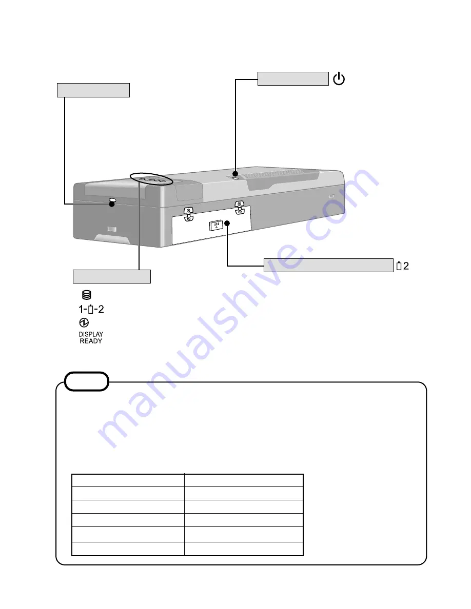
Names and Functions of Parts
The illustrations shown may differ from the actual physical appearances.
Second Battery Pack Slot
Hard disk status
Battery pack status
Power status
Wireless display status
Before using the computer for the first
time, carefully read the [Limited Use Li-
cense Agreement]. If you agree to the
conditions, remove the seal.
Power Switch
Security Lock
A Kensington cable can be con-
nected to prevent theft of your
computer. For more information,
please read the manual that comes
with the cable.
LOCK
If a battery pack is inserted when the computer is off (under the condition there is no
battery pack in the computer), LED indicators will blink five times. You can confirm the
remaining battery power by looking at the LED indicators. Since the remaining battery
power is displayed for one battery pack, insert battery packs one at a time for confirma-
tion purposes. You can also confirm the remaining battery power in the same way when
the computer is on after a battery pack is inserted.
NOTE
LED Indicators
LED Indicators
Non-blinking
One indicator-blinking
Two indicators-blinking
Three indicators-blinking
Four indicators-blinking
Remaining battery power
0%
1%
~
20%
21%
~
50%
51%
~
80%
81%
~
100%
5-1
Содержание CF-07 Series
Страница 3: ... RU 8 6 1 2 2 ...
Страница 4: ...2 3 ...
Страница 21: ...9 6 System Memory Map ...
Страница 24: ...8 Diagnosis Procedure Basic Procedures 11 ...
Страница 41: ...Example ALT F brings up the File menu Input screen Order of test flow selection 16 5 ...
Страница 43: ...14 Wiring Connection Diagram 17 ...
Страница 47: ...16 Exploded View 1 Exploded View 1 2 19 1 ...
Страница 48: ...2 Exploded View 2 2 19 2 ...
Страница 64: ......
Страница 65: ......
Страница 66: ......
Страница 67: ......
Страница 68: ......
Страница 69: ......
Страница 70: ...CF 07LZ5ZYXM 1 Schematic Diagrams Upper Main 1 CPU 1 2 ...
Страница 71: ...Upper Main 2 CPU 2 2 2 ...
Страница 72: ...U s 3 pper Main 3 Resister ...
Страница 73: ...U k 4 pper Main 4 Cloc ...
Страница 74: ...U 5 pper Main 5 GMCH M 1 2 ...
Страница 75: ...pper Main 6 GMCH M 2 2 U U 6 ...
Страница 76: ...pper Main 7 ON Board Memory 7 U U ...
Страница 77: ...pper Main 8 Micro DIMM 8 U U ...
Страница 78: ...Upper Main 9 iCH2 M 1 2 9 ...
Страница 79: ...Upper Main 10 iCH2 M 2 2 10 U U ...
Страница 80: ...pper Main 11 Terminator 11 U U ...
Страница 81: ...U Upper Main 12 HDD 12 ...
Страница 82: ...Upper Main 13 BIOS 13 U U ...
Страница 83: ...Upper Main 14 PCMCIA Controller 14 ...
Страница 84: ...pper Main 15 Slot 1 WLSD Connector 15 U U ...
Страница 85: ...pper Main 16 LED Connector 16 U ...
Страница 86: ...Upper Main 17 Base Connector 17 ...
Страница 87: ...Upper Main 18 VCPUCORE VC25 18 ...
Страница 88: ...pper Main 19 Power Circuit 19 U U ...
Страница 89: ...Upper Main 20 Modem Controller 20 ...
Страница 90: ...pper Main 21 Line Codec 21 U U ...
Страница 91: ...Lower Main 1 Connector 22 L L ...
Страница 92: ...ower Main 2 Super I O 23 L ...
Страница 93: ...Lower Main 3 COM Connector 24 L L ...
Страница 94: ...Lower Main 4 Wireless Connector 25 L L ...
Страница 95: ...Lower Main 5 KBC 26 L L ...
Страница 96: ...Lower Main 6 Q AW for Doc 27 L L ...
Страница 97: ...Lower Main 7 Doc Connector 28 ...
Страница 98: ...Lower Main 8 EC 29 ...
Страница 99: ...L LLower Main 9 Reset 30 ...
Страница 100: ...L Lower Main 10 DC IN 31 ...
Страница 101: ...L Lower Main 11 VD3 VD5 32 ...
Страница 102: ...L Lower Main 12 Power Circuit2 33 ...
Страница 103: ...L Lower Main 13 BATT SW 34 ...
Страница 104: ...Lower Main 14 RF DC DC 35 ...
Страница 105: ...Lower Main 15 Charger 36 ...
Страница 106: ...Lower Main 16 Doc Power 37 ...
Страница 107: ...Lower Main 17 VD18 38 ...
Страница 108: ...Serial Connector 39 S S ...
Страница 109: ...D U Sub Connector 40 D DDD ...
Страница 110: ...D U Docking Connector 41 D DD ...
Страница 111: ...D U Sub Connector 42 D D ...
Страница 112: ...43 ...
Страница 113: ...44 ...
Страница 114: ...45 ...
Страница 115: ...W W 46 ...
Страница 116: ...Wireless 5 RF IF Mixer 1st Lo 47 ...
Страница 117: ...48 ...


