background image

31

30

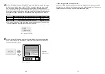
Click the “RAM” radio button or “RAM+ROM” radio button to select the type of memory
in which the data will be saved. (Fig.13) If “RAM” is selected, the image data is saved
only in the frame memory and so it cannot be used after the AW-SW350 power has
been turned off and back on again. If “RAM+ROM” is selected, the image data is saved
in the flash memory and so it can be used after the AW-SW350 power has been turned
off and back on again. However, the actual transfer takes longer than when “RAM” is
selected.

Click the “Write USB” button to start transferring the image data. After the completion
of the transfer, monitor the AW-SW350's PGM output and check that the image data
has been transferred. (Fig.14)

6

5

— When images could not be transferred —
If an error resulted or images could not be transferred because a cable was connected or
disconnected, turn off the switcher's power and exit the application program. Then turn the
switcher's power back on again and start up the application again.

Status after power has been turned off and back on again

Transfer time

RAM

Transferred image data cannot be used

Approx. 10 sec.

RAM+ROM

Transferred image data can be used

Approx. 60 sec.

The transfer times given in the above table are approximations only. The actual time
taken will depend on the performance of the host computer.

Fig.13  Memory selection

Click the

button

AW-SW350
program output

Fig.14  PGM check

Содержание AWSW350P - SWITCHER

Страница 1: ...AIN SOURCE IN5 FMEM KEY AUTO CLIP SF2 YLW MWR CYN INT GRN FRZ MGT RED BLE N N R R INV H SC SC FINE ON OFF A 1 2 3 4 5 FMEM BLACK MIX FRZ WIPE AUTO TAKE BAR COLOR B B Live Switcher AW SW350 Model No AW SW350P Before attempting to connect operate or adjust this product please read these instructions completely Live Switcher ...

Страница 2: ... on the bottom of the unit indicates safety information FCC Note This device complies with Part 15 of the FCC Rules To assure continued compliance follow the attached installation instructions and do not make any unauthorized modifications This equipment has been tested and found to comply with the limits for a class A digital device pursuant to Part 15 of the FCC Rules These limits are designed t...

Страница 3: ...e risk of electric shock don t remove cover or back unless you are a qualified personnel Refer all mountings connections servicing to qualified service personnel No water or moisture inside Do not let water or moisture into the product or expose it to moisture to prevent a fire and electric shock If you see smoke or smell an odor from the product if water or other foreign matter gets inside if it ...

Страница 4: ...d the unit can be used as a wideband switcher with minimal deterioration in image quality resolution of 800 lines Genlock The switcher enables genlocking to the reference sync signal of an external device Furthermore by using its BB output the system can be upgraded using the synchronization of the switcher as a reference Image Transfer Soft Keys and Linear Keys Inside the switcher AW SW350 has a ...

Страница 5: ...nel to be recorded Once the setting has been performed keep pressing MWR while holding down the SETTING switch until the nine switches go off The recorded statuses will be reproduced when the power is next turned on INT This is used to restore the initial settings which were established at the factory Keep pressing INT while holding down the SETTING switch until the nine switches go off The same s...

Страница 6: ...us signal to the selected A bus signal WH1 YLW WH2 CYN RED WH3 GRN BLE MGT Example Selected wipe pattern UTransition Time Setting Controls TRANSITION TIME These controls are used to set the transition time during auto fader operations AUTO TAKE This is used to set the transition time of MIX or WIPE when the AUTO TAKE u Switch has been pressed Any transition time from 0 to about 10 seconds can be s...

Страница 7: ...to align the color phase A more accurate adjustment can be achieved using a vectorscope A Bus Input Selection Switches To select A bus video signals When a switch is pressed it lights and indicates that the corresponding signal is selected qB Bus Input Selection Switches These are used to select the B bus video signals When a switch is pressed it lights to indicate that the corresponding signal is...

Страница 8: ...e A bus signals are output Both A and B light when the Fader Lever is between the A and B sides since both A bus and B bus signals are output 15 BBOUT GLIN BBOUT PVW OUT TALLY INCOM PGM OUT 2 5 4 DC 12V IN SET UP USB EXT TAKE PGM Y C OUT 1 3 4 2 GND 3 2 1 1 1 75Ω AUTO 2 3 4 5 1 2 3 4 5 VIDEO IN OUT Y C IN REAR PANEL pVideo Signal Input Jacks 1 to 5 VIDEO IN 1 2 3 4 5 These jacks are to input compo...

Страница 9: ...ignals to these jacks in using them as video input signals AVideo Output Connectors PGM OUT 1 2 Two sets of composite signals BNC consisting of the switcher s main output together with the wipe mix key or other effects added are output from these output jacks SPreview Output Connector PVW OUT When the switcher is used for live applications this connector enables the next operation to be previewed ...

Страница 10: ...d A delay of up to one frame is generated in the switcher output Due to what is involved in the signal processing the signal band is narrower than at the OFF position OFF The input signal source must be synchronized with the system Use the switcher s black burst signal output to apply genlock to the camera or other device In this case perform the phase horizontal phase color phase adjustments for ...

Страница 11: ...er to Operation Method SPECIFICATIONS In order for the host computer to run the USB image transfer program used with the AW SW350 it must satisfy the following system requirements Image files in two formats the bitmap format bmp and JPEG format jpg jpeg can be used with the USB image transfer program for the AW SW350 Also required separately when using the image transfer function is the A B type U...

Страница 12: ... recognizes the AW SW350 as shown in Fig 2 the Found New Hardware Wizard automatically starts up 3 2 1 When the screen for specifying the driver loading directory appears as shown in Fig 3 specify the DRIVER folder of the drive where the CD ROM supplied with the AW SW350 was inserted and load the driver In this example E is the drive used When the device driver has been loaded a screen similar to ...

Страница 13: ...this example E is the drive used Run the Microsoft Net Framework setup file E JPN DOTNETFX EXE The installer program shown in Fig 6 now starts Proceed with the installation by following the installer instructions Run the setup program E JPN SETUP EXE 4 3 2 1 In order to confirm that the device driver has been installed successfully it is recommended that you open the Device manager as shown in Fig...

Страница 14: ... SW350 is started up When the Open File button is clicked the file selection dialog box shown in Fig 10 appears Select the image file BMP JPG or JPEG to be transferred and click OK 3 2 1 The installer program shown in Fig 7 now starts Proceed with the installation by following the installer instructions This completes the installation of the application program 6 5 Fig 7 Application program instal...

Страница 15: ...be displayed The frame outlining what can be displayed appears Move the frame to the position where the image to be displayed is framed When the image is smaller than the number of pixels that can be displayed Drag the image displayed in the screen display area and drop it to change its position Fig 11 4 When the image is larger than the number of pixels that can be displayed Drag the frame displa...

Страница 16: ...transfer monitor the AW SW350 s PGM output and check that the image data has been transferred Fig 14 6 5 When images could not be transferred If an error resulted or images could not be transferred because a cable was connected or disconnected turn off the switcher s power and exit the application program Then turn the switcher s power back on again and start up the application again Status after ...

Страница 17: ...IDEO OUT Convertible Camera AW E600 VIDEO OUT Camera Color monitors Camera or character generator for key synthesis Signal generator When a signal generator is used to generate the reference signals for the system AC adaptor AW PS505 QFS switch ON WGLIN BBOUT switch GLIN VCR etc BBOUT GLIN BBOUT PVW OUT TALLY INCOM PGM OUT 2 5 4 DC 12V IN SET UP USB EXT TAKE PGM Y C OUT 1 3 4 2 GND 3 2 1 1 1 75Ω A...

Страница 18: ...AUTO 2 3 4 5 1 2 3 4 5 VIDEO IN OUT Y C IN AW SW350 Convertible Camera AW E600 Convertible Camera AW E600 Convertible Camera AW E600 OUT VIDEO OUT VIDEO OUT Convertible Camera AW E600 VIDEO OUT These switches operate whether the FS switch is in the ON or OFF position Color monitors Connected with USB cable AC adaptor AW PS505 VCR etc Camera or character generator for key synthesis Camera ...

Страница 19: ...AMERA CONTROL OUT VIDEO OUT PAM TILT CONTROL OUT S VIDEO OUT VIDEO IN G L OUT 4 3 2 1 5 D C 1 2 V I N TO CAMERA PAM TILT HEAD TO CONTROL PANEL PREVIEW OUT SEE MANUAL Pan tilt head cameras 1 to 4 To pan tilt head AW PH300A Camera AW E300 E600 E800A Multi port hub AW HB505 Multi hybrid control panel AW RP505 AC adaptor AW PS301 AC adaptor AW PS505 Preview monitor The FS switch may be in either the O...

Страница 20: ... OF F A 1 2 3 4 5 FM EM BLAC K WI PE AU TO TAK E BA R CO LOR B B MIX FR Z Rack mounting parts Mounting screw Mounting screw Holes for connecting plate Bottom Connecting plate INFORMATION RELATED TO SYSTEM UPGRADES 1 Switcher phases 1 Video signal output phase frame synchronizer is OFF 2 Video signal input phase frame synchronizer is ON 3 Genlock adjustment range 2 TALLY INCOM connectors Use a Mini...

Страница 21: ...pe Mix time adjustable Key synthesis Self Key Linear Key Intercom 1 to 5 6 pin connector 3 4 wire selectable Intercom jack M6 jack Tally control 1 to 5 open collector output Color bar Internal SMPTE Black Color selectable White and black signals Internal Frequency response FS ON 6 0MHz 1 dB 3dB FS OFF 10 0MHz 1 dB 3dB S N FS ON More than 58 dB FS OFF More than 65 dB DG DP FS ON 2 2 FS OFF 1 5 1 5 ...

Страница 22: ...43 42 Memo ...
Страница 23: ...vernment Marketing Department 52 West Gude Drive Rockville MD 20850 301 738 3840 Broadcast PARTS INFORMATION ORDERING 9 00 a m 5 00 p m EST 800 334 4881 24 Hr Fax 800 334 4880 Emergency after hour parts orders 800 334 4881 TECHNICAL SUPPORT Emergency 24 Hour Service 800 222 0741 Panasonic Canada Inc 5770 Ambler Drive Mississauga Ontario L4W 2T3 905 624 5010 Panasonic de Mexico S A de C V Av angel ...

Отзывы: