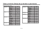
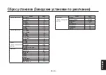
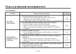
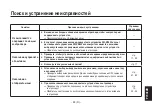
background image

- 79 (R) -

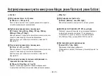
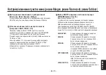
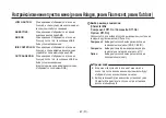
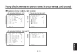
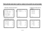
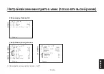
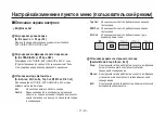
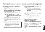
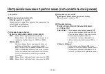
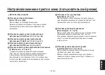
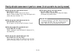
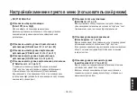
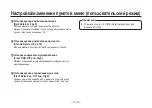
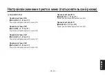
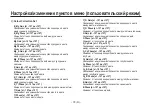
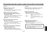
 Colour Correction Set

B_Mg Gain [)+ –127 () +127]

$     *      ' "  
    .

B_Mg Phase [)+ –127 () +127]

;       ' "      
.

Mg Gain [)+ –127 () +127]

$     *    ' " .

Mg Phase [)+ –127 () +127]

;     ' " .

Mg_R Gain [)+ –127 () +127]

$     *      ' "  
    .

Mg_R Phase [)+ –127 () +127]

;       ' "      
.

R Gain [)+ –127 () +127]

$     *    ' " .

R Phase [)+ –127 () +127]

;     ' " .

R_Yl Gain [)+ –127 () +127]

$     *      ' "  
     .

R_Yl Phase [)+ –127 () +127]

;       ' "       .

Yl Gain [)+ –127 () +127]

$     *     ' " .

Yl Phase [)+ –127 () +127]

;      ' " .

Yl_G Gain [)+ –127 () +127]

$     *      ' "  
       .

Yl_G Phase [)+ –127 () +127]

;       ' "         .

G Gain [)+ –127 () +127]

$     *      ' " .

G Phase [)+ –127 () +127]

;       ' " .

G_Cy Gain [)+ –127 () +127]

$     *      ' "  
      '.

G_Cy Phase [)+ –127 () +127]

;       ' "        
'.

Cy Gain [)+ –127 () +127]

$     *    '' " .

Cy Phase [)+ –127 () +127]

;     '' " .

Cy_B Gain [)+ –127 () +127]

$     *      ' "  
  '  .

Cy_B Phase [)+ –127 () +127]

;       ' "    '  .

B Gain [)+ –127 () +127]

$     *     " .

B Phase [)+ –127 () +127]

;      " .

*+)C6/? '36+)0 N (')19?)0+19*6C /)

Содержание AW-HE870E

Страница 1: ...D Convertible Camera DEFINITION HIGH Operating Instructions HD Convertible Camera Model No AW HE870E Before operating this product please read the instructions carefully and save this manual for future use 3TR006376BAA Installation instructions provided ...

Страница 2: ...OT BE EXPOSED TO DRIPPING OR SPLASHING AND THAT NO OBJECTS FILLED WITH LIQUIDS SUCH AS VASES SHALL BE PLACED ON THE APPARATUS CAUTION TO REDUCE THE RISK OF FIRE OR SHOCK HAZARD AND ANNOYING INTERFERENCE USE THE RECOMMENDED ACCESSORIES ONLY ENGLISH VERSION w DO NOT REMOVE PANEL COVERS BY UNSCREWING To reduce the risk of electric shock do not remove the covers No user serviceable parts inside Refer ...

Страница 3: ...ectly will help to save valuable resources and prevent any potential negative effects on human health and the environment which could otherwise arise from inappropriate waste handling Please contact your local authority for further details of your nearest designated collection point Penalties may be applicable for incorrect disposal of this waste in accordance with national legislation For busines...

Страница 4: ...ing the external synchronizing signals 24 wConnection of the Indoor Pan tilt Head AW PH360 25 wConnection of the Indoor Pan tilt Head AW PH400 28 wConnection of the Indoor Pan tilt Head AW PH405 31 wConnection of the Outdoor Pan tilt Head AW PH650 34 How to operate the system 37 wControl exercised from the Remote Operation Panel AW CB400 37 wControl exercised from the Multi Function Controller AW ...

Страница 5: ...Menu item setting changing User Mode 68 wSub menu User Mode 68 wDescription of the setting screen 71 Changing the settings 84 wChanging the format settings 84 wChanging the component setting 85 wSetting the EBU matrix 86 Setting to initial set Factory presets 87 wSetting to initial set 87 wInitial settings of the setting items Factory preset values 88 Troubleshooting 91 Appearance 96 Specification...

Страница 6: ...devices such as a remote control panel or a pan tilt head allowing for system development according to the intended use p The camera can be used for even more applications by inserting an option card p In order to protect the environment when the HD convertible camera is to be discarded at the end of its service life ask a specialized contractor to dispose of it properly Note Standard accessories ...

Страница 7: ...ction functions Noise during imaging on computer screens is reduced by the Synchro Scan function An optimum condition can be selected to suit the intended use from among four use modes Halogen Fluorescent Outdoor and User Supports the SDI card option 2 AW HHD870 Adopts operating procedures that are the same as those of our convertible cameras 3 Our pan tilt heads 4 and control panels can be used 5...

Страница 8: ...eared picture unique to the CCD The ATW function under fluorescent illumination can adversely change the white balance p There is a cooling fan inside The cooling fan is a consumable part Replace it 3 to 5 years after installation as a general rule When the cooling fan malfunctions the Fan Error message is displayed when the power is turned ON When the Fan Error message is displayed request replac...

Страница 9: ...ole uncovered p Do not touch the surface of the lens or prism p Do not use strong of abrasive detergents when cleaning the camera body p Do not aim the camera toward the sun no matter whether it is turned on or not p Do not expose the camera or other units to rain or moisture and do not try to operate the equipment in wet conditions Do not operate the camera if it becomes wet p Do not operate the ...

Страница 10: ... it is dirty In case the dirt is hard to remove use mild detergent and wipe gently p Use caution when operating the camera in the vicinity of spot lights or bright lights as well as light reflecting objects and surfaces p Take immediate action if ever the camera should become wet Turn the power off and have the unit checked by an authorized service facility p Follow normal safety precautions to av...

Страница 11: ...t temperature 10 C to 45 C range p Locations near the air outlet of an air conditioner or near a door where the camera will be exposed to incoming outside air or other locations where the temperature is subject to sudden change since these locations may cause the lens area to cloud over and or condensation to form p Locations that are subject to significant vibration such as on top of a car p Loca...

Страница 12: ...e provided refer to the next page p Attach the drop prevention wire to the camera mounting screw hole Inch screw Tightening the mounting screws Tighten using the torque levels shown in the table below After tightening check for play and unsteadiness Screws Clamping torque Mounting screws Inch screws 2 0 N m 20 kgf cm The connection and installation should be done by qualified service personnel or ...

Страница 13: ...BAB 600 3CN001064BAC Mounting screws Inch screws 1 4 20UNC 2 For mounting the camera Determine the length of these screws by factoring in the thickness of the camera mounting bracket Mounting screws M6 for installation end wire At the installation location be absolutely sure to use the anchor bolts and ensure that the strength of the installation surface is at least ten times the total mass of all...

Страница 14: ...r functions wFront view Top view Rear view Bottom view Front view Top view Bottom view 32 mm 20 mm 10 mm 18 mm Rear view 20 mm 32 mm Mounting screws Inch screws 1 4 20UNC Depth 10 mm Mounting screws Inch screws 1 4 20UNC Depth 10 mm 17 5 mm ...

Страница 15: ...r at least 3 seconds The menu screen is cleared when the switch is pressed for at least 3 seconds while the menu is displayed When this switch is pressed while an item is being changed on a sub menu screen the set values will revert back to those prior to making changes ENTER AWB switch ENTER AWB If this switch is pressed on the main menu screen a sub menu screen with selection items appears and i...

Страница 16: ...nged on a sub menu screen the value is adjusted lower When the menu is not displayed the colour bar and the shooting conditions are indicated by pressing the switch for about 2 seconds Video output connector VIDEO OUT A composite video signal is provided at this connector 1 V p p 75 j BNC connector Iris connector IRIS Connect the IRIS cable of the motor drive lens such as the AW LZ17MD9AG and AK L...

Страница 17: ...le provided with the main unit Note Cable clamp Clamp the DC cable with ø5 5 plug connected to the DC 12 V input connector to prevent it from slipping out Be absolutely sure to secure the DC cable using the cable clamp G L input connector G L IN External synchronizing signals BB are to be supplied to this connector when the camera is to be synchronized with the external synchronizing signals Three...

Страница 18: ...cap 2 Mount the lens on the camera and rotate the lens fixing ring knob clockwise in order to fix the lens securely 3 Connect the IRIS cable to the IRIS connector on the back panel of the camera When the pan tilt head has been used p Connect the remote cable of the lens to the LENS IF 1 terminal on the pan tilt head When the SDI card AW HHD870 is installed without using the pan tilt head p Connect...

Страница 19: ...our own drop prevention wire mounting screws and washers Camera mounting screw holes Inch screws 1 4 20UNC Depth 10 mm Camera mounting adapter Preventing the camera from falling or coming off p When attaching a camera to the pan tilt head AW PH360 AW PH400 AW PH405 AW PH650 follow the directions in the Operating Instructions to fix the camera firmly in position In addition link the camera to the p...

Страница 20: ...the total mass including the mounting bracket camera lens and cables does not exceed 8 kg p Ensure that a drop prevention wire is installed in such a way that the drop distance does not exceed 150 mm p Tighten the mounting screws using the torque levels shown in the table to the below and then check for play and unsteadiness Screws Clamping torque Mounting screws Inch screws 2 0 N m 20 kgf cm p Do...

Страница 21: ...d as well be absolutely sure to prevent the camera from falling off by using the screw in the tripod or other such means p When mounting the camera on a surface above the camera do not block the ventilation holes of the cooling fan p Ensure that the total mass including the mounting bracket camera lens and cables does not exceed 8 kg p Ensure that a drop prevention wire is installed in such a way ...

Страница 22: ...oles refer to Major operating controls and their functions on page 13 p When using the camera mounting screw holes on the camera s top surface when mounting the camera by suspending it take care not to block the ventilation holes of the cooling fan p When using the camera mounting screw holes on the camera s top surface when mounting the camera by suspending it attach the drop prevention wire to t...

Страница 23: ...tor on the unit with the device equipped with HD SD component signal input connectors p Composite signals from the VIDEO OUT connector and component signals from the I F REMOTE connector can be output at the same time p Use the DC cable with ø5 5 plug supplied with the AW HE870 for connection to the 12 V input connector AC Adapter AW PS505A VIDEO OUT connector 75 j coaxial cable Composite video in...

Страница 24: ... unit through the connecting cables optional accessory AW CA50T8 or AW CA50T9 RS 422 RS 232C converter p The distance between the ROP and the AW CA50T8 or AW CA50T9 RS 422 RS 232C converter can be extended up to a maximum of about 1000 m using a 10BASE T equivalent to UTP category 5 straight cable Zoom lens Iris control DC cable provided with AW HE870 AC Adapter AW PS505A AC Adapter AW PS505A Moni...

Страница 25: ...he selected video output format Format will be synchronized 1080i 720p or 576i When selecting an HD format 1080i or 720p neither the VIDEO OUT signal composite signal nor the Y C signal output from the AW CA50T8 S Video terminal will be synchronized with the external synchronizing signal To synchronize the VIDEO OUT signal composite signal or the Y C signal output from the AW CA50T8 S Video termin...

Страница 26: ... or their equivalent p Connect the CONTROL OUT TO PAN TILT HEAD terminals P1 to P5 of the AW RP400 and the RP terminal of the AW PH360 with a 10BASE T straight cable when using the AW RP400 pan tilt control panel The maximum extension distance is 500 m when using UTP category 5 cables or their equivalent p Use the camera cable provided with the pan tilt head to connect the AW PH360 to the unit p C...

Страница 27: ...0p analogue component signals cannot be output from the AW PH360 p Refer to the operating instructions of the AW PH360 for details relating to internal switch settings etc of the pan tilt head p Use the AW LZ17MD9AG lens when using the camera mounted on the pan tilt head AW PH360 Lenses other than the AW LZ17MD9AG cannot be used Do not mount the camera on the AW PH360 when the AK LZ20M85G is insta...

Страница 28: ... cross section 1 25 mm2 or more Pan Tilt Control Panel AW RP400 Remote Operation Panel AW CB400 Multi Function Controller AW RP655 Multi Hybrid Control Panel AW RP555 Pan tilt head camera control signals 10BASE T straight cable Monitor AC Adapter AW PS505A AC Adapter AW PS505A AC Adapter AW PS505A When an SDI card AW HHD870 has been installed Monitor Y Pr Pb SD component signal The SDI connector i...

Страница 29: ...uivalent Connect the PAN TILT HEAD terminal of the protocol converter AW IF400 and the RP terminal of the AW PH400 with a 10BASE T straight cable The maximum extension distance is 500 m when using UTP category 5 cables or their equivalent p Connect the CONTROL OUT TO PAN TILT HEAD terminals P1 to P5 of the AW RP400 and the RP terminal of the pan tilt head using a 10BASE T straight cable when using...

Страница 30: ...connector on the AW PH400 p Use a coaxial cable to connect the SDI connector on the AW PH400 to the SDI input connector on the colour monitor p HD 1080i or 720p analogue component signals cannot be output from the AW PH400 Note p AW IF400 Switch settings when the AW RP555 AW RP655 is used SW1 SW2 SET UP 1 2 3 Tilt range 4 OFF OFF ON OFF ON 300 deg OFF 190 deg OFF System configuration Connections ...

Страница 31: ... Monitor Protocol Converter AW IF400 Pan Tilt Control Panel AW RP400 Remote Operation Panel AW CB400 Multi Function Controller AW RP655 Multi Hybrid Control Panel AW RP555 Pan tilt head camera control signals 10BASE T straight cable AC Adapter AW PS505A Monitor AC Adapter AW PS505A AC Adapter AW PS505A AC Adapter AW PS505A AC power cable supplied with AW PH400 To the LENS I F 1 connector Iris cont...

Страница 32: ...TROL OUT TO PAN TILT HEAD terminals P1 to P5 of the AW RP400 and the CONTROLLER terminal of the protocol converter AW IF400 using a 10BASE T straight cable when using the AW RP400 pan tilt control panel The maximum extension distance is 500 m when using UTP category 5 cables or their equivalent Connect the PAN TILT HEAD terminal of the protocol converter AW IF400 and the RP terminal of the AW PH40...

Страница 33: ...le to connect the SDI connector on the AW PH405 to the SDI input connector on the colour monitor p When transmitting HD 1080i or 720p analogue component signals the switch inside the AW PH405 main unit must be set to the HD position the operation of the cable compensation circuit is not involved Consult your dealer Note p AW IF400 Switch settings when the AW RP400 is used SW1 SW2 SET UP 1 2 3 4 OF...

Страница 34: ... Converter AW IF400 Pan Tilt Control Panel AW RP400 Remote Operation Panel AW CB400 Multi Function Controller AW RP655 Multi Hybrid Control Panel AW RP555 Pan tilt head camera control signals 10BASE T straight cable AC Adapter AW PS505A Monitor AC Adapter AW PS505A AC Adapter AW PS505A AC Adapter AW PS505A Iris control cable When an SDI card AW HHD870 has been installed Zoom focus control cable To...

Страница 35: ...CONTROL OUT TO PAN TILT HEAD terminals P1 to P5 of the AW RP400 and the CONTROLLER terminal of the protocol converter AW IF400 using a 10BASE T straight cable when using the AW RP400 pan tilt control panel The maximum extension distance is 500 m when using UTP category 5 cables or their equivalent Connect the PAN TILT HEAD terminal of the protocol converter AW IF400 and the RP terminal of the AW P...

Страница 36: ...onnector on the colour monitor p When transmitting HD 1080i or 720p analogue component signals set SW2 and SW3 on the COMP circuit board to the HD position The cable compensation circuit will not be activated even if SW1 is set to ON at this time so use this switch at the OFF setting p For the connections inside the housing and other details refer to the operating instructions of the AW PH650 Note...

Страница 37: ... relay adapter Protocol Converter AW IF400 Pan Tilt Control Panel AW RP400 Remote Operation Panel AW CB400 Multi Function Controller AW RP655 Multi Hybrid Control Panel AW RP555 Pan tilt head camera control signals 10BASE T straight cable AC Adapter AW PS505A Monitor AC Adapter AW PS505A AC Adapter AW PS505A AC Adapter AW PS505A Pb Y MULTI SDI OUT POWER When an SDI card AW HHD870 has been installe...

Страница 38: ...or when FAST has been selected as the status of the IRIS dial reaction speed For switching DTL ON and OFF The LOW HIGH selection can be made on the LCD menu when turned ON For selecting GAIN 0dB L M H or AGC The selected button lights 2 The L M H buttons can be set in increments of 1 dB between 0 dB and 18 dB on the LCD of the CB400 3 11 Furthermore the MAX GAIN setting of the AGC can be performed...

Страница 39: ...s disconnected because the OPERATE switch has been turned OFF CAMERA SELECT has been switched the communication cable has been disconnected etc 6 The lamp of the ABB or AWB switch flashes while automatic white balance or automatic black balance is being executed respectively When ABB or AWB is completed successfully the corresponding lamp goes off when it is not completed successfully it lights up...

Страница 40: ...o scroll up the item list Press the D button of the OPTION SW to scroll down the selected item Press the B button of the OPTION SW to confirm the item selection Once an item is selected change the set value of the AW HE870 Press the C button of the OPTION SW to change the set value in the positive direction and press the D button of the OPTION SW to change the set value in the negative direction P...

Страница 41: ...n lights up at the BAR setting This is used to switch between AUTO and MANU for the gain The GAIN button lights when the AUTO setting is selected For switching WHITE BAL A B or ATW 1 For executing AWB 2 3 These are used for menu operation Switch between gain adjustment mode and pedestal adjustment mode Jog dial R When the LCD panel is in the gain adjustment mode Adjust the B GAIN setting 150 to 15...

Страница 42: ...r Bar is being displayed 4 Flashing stops when communication is disconnected because the OPERATE switch has been turned OFF CAMERA SELECT has been switched the communication cable has been disconnected etc 5 The switch lights without ABB being executed when the Colour Bar is being displayed 6 SCENE FILE CAM BAR and GAINUP of each SCENE as well as the W B MODE R B GAIN and T R B PED statuses are sy...

Страница 43: ...s installed without using the pan tilt head Procedure for camera menu operation AW RP655 Press the MENU button to set the LCD panel display to the menu mode Turn the jog dial main to select the CAMERA SETTING Press the OK button The SCENE Selection menu display appears on the LCD panel SCENE HALOGEN OK Key Select the preferred scene and press the OK button The right display appears on the LCD pane...

Страница 44: ...on to change the data setting in increments of 10 it is not possible to change the data setting beyond setting range of data Push the jog dial main down to enter the settings To exit the camera menu press the MENU button or R B GAIN PED button p When controlling the AW HE870 the G L SETTING is not displayed The G L must be set using the camera menu of the AW HE870 p It may be necessary to upgrade ...

Страница 45: ...ence of GAIN AUTO 0dB L 9dB H 18dB and the mode is displayed by the LEDs as shown below ON LED lit OFF LED off GAIN button MANU L LED MANU H LED AUTO ON OFF OFF 0dB OFF OFF OFF LOW OFF ON OFF HIGH OFF OFF ON Others OFF ON ON Each time the MODE button is pressed the setting is switched between CAM and BAR The MODE button lights up at the BAR setting For selecting the cameras and pan tilt head syste...

Страница 46: ...switch lights without AWB being executed when the white balance mode of the main unit is ATW PRESET 3200K or PRESET 5600K or when the Colour Bar is being displayed 3 Flashing stops when communication is disconnected because the OPERATE switch has been turned OFF CAMERA SELECT has been switched the communication cable has been disconnected etc 4 The switch lights without ABB being executed when the...

Страница 47: ...2 seconds The camera menu of the AW HE870 is displayed on the monitor Select a menu item Press the YES button to scroll down the selected item Press the NO button to scroll up the selected item Press the ITEM button to confirm the item selection Once an item is selected change the set value of the AW HE870 Press the YES button to change the set value in the negative direction and press the NO butt...

Страница 48: ...en mode Suited to indoor shooting such as at weddings parties lecture meetings events etc Settings can be changed using a simple menu q Fluorescent mode Suited to indoor shooting under fluorescent lighting Settings can be changed using a simple menu q Outdoor mode Suited to outdoor shooting Settings can be changed using a simple menu q User mode Settings can be changed using a detail menu ...

Страница 49: ...h or the DOWN BAR switch is pressed Move the cursor to the desired use mode 3 Press the ENTER AWB switch The selecting use mode comes into effect After the use mode setting menu is shown for about 5 seconds the camera returns to be ready for operation Then the camera operates in the selected use mode MENU switch ENTER AWB switch UP ABB switch DOWN BAR switch Use Mode Set Halogen Fluorescent Outdoo...

Страница 50: ...htness has been changed p Once the white balance has been adjusted it need not be adjusted again when the camera is going to be used under the same conditions 6 Adjust the black balance p The black balance must be adjusted when the camera is used for the first time and when it is going to be used again after it has not been used for a prolonged period p It must be adjusted when the ambient tempera...

Страница 51: ... focus ring and the flange back adjust ring alternately for the best focus within the zooming range Tighten the flange back lock knob upon completion of focusing wIris gain control in a lens p An iris gain control hole G S is usually provided in the front of the lens Adjustment of the iris gain with a screwdriver through the hole may be done as follows Shape and location of the hole may vary depen...

Страница 52: ...amera to the ambient conditions p The preset conditions will be renewed whenever you input new conditions 1 Select the white balance mode either AWB A or AWB B 2 Aim the camera at a white object a white wall or a white handkerchief and zoom in to enlarge the image as much as possible For white balance setting aim the camera at a white object and try to position it in the centre of the monitor scre...

Страница 53: ...W might not function properly when high brightness light ex fluorescent lamp beams into a screen p White balance may not be accurately set if there is no white object in the scene being shot Notes q Manual white balance setting Manual setting is possible in User Mode only 1 Select the white balance mode either AWB A or AWB B by menu 2 Aim the camera at a large white object to set the automatic whi...

Страница 54: ...ing setting will be automatically reset to 0 after setting the black balance Painting setting in only User Mode Press the UP ABB switch for over 2 seconds and the black balance will be set in 30 seconds In user mode black balance fine adjustment can be performed by changing the R pedestal B pedestal setting with the Painting item of Colour Set sub menu after setting the black balance UP ABB switch...

Страница 55: ...e same Please contact your dealer for the adjustment 1 Close the lens 2 Select Pedestal item in the Brightness Set sub menu 3 Set the pedestal level to 0 035 V with the UP ABB switch or the DOWN BAR switch UP ABB switch DOWN BAR switch Brightness Set A Iris Level 0 A Iris PEAK AVG 0 A Iris Area Top Cut Shutter Mode Step Step Synchro Off Gain 0dB AGC Max Gain Pedestal 0 Return 0 035 V Adjustment ...

Страница 56: ...f the camera menu S Video terminal will be synchronized with the external synchronizing signal To synchronize the VIDEO OUT signal composite signal or the Y C signal output from the AW CA50T8 S Video terminal with the external synchronizing signal use 576i as the video output format selected from the camera menu Notes p When horizontal phase adjustment is moved colour phase is also moved Adjust co...

Страница 57: ... by camera menu Press the DOWN BAR switch for over 2 seconds to display the colour bar Press the MENU switch for 3 seconds or more to display the main menu Press the UP ABB switch or the DOWN BAR switch to move the cursor to G L Set then press the ENTER AWB switch to display the G L Set sub menu Select H Phase on the G L Set sub menu Adjust the horizontal phase with the UP ABB and DOWN BAR switch ...

Страница 58: ...mera menu Press the DOWN BAR switch for over 2 seconds to display the colour bar Press the MENU switch for 3 seconds or more to display the main menu Press the UP ABB switch or the DOWN BAR switch to move the cursor to G L Set then press the ENTER AWB switch to display the G L Set sub menu Select SC Coarse on the G L Set sub menu Make coarse adjustment with the UP ABB switch and the DOWN BAR switc...

Страница 59: ...o individual scenes p Characters displayed on the menu may be cut off depending on the monitor used Notes q Setting when using the camera by itself 1 Keep the MENU switch depressed for 3 seconds or more to display the main menu of each use mode For selecting the use mode refer to page 47 2 Each time the UP ABB switch or DOWN BAR switch is pressed the selected item moves up or down 3 When the ENTER...

Страница 60: ...N BAR switch q Main menu screen Main menu of Halogen Fluorescent Outdoor Mode Halogen Mode Set Brightness Set Colour Set Detail Set G L Set Other Set 1 Other Set 2 Initialize Data Displays the use mode Main menu of User Mode User Mode Set Brightness Set Colour Set HD Detail Set SD Detail Set Colour Matrix Set Colour Correction Set G L Set Other Set 1 Other Set 2 Initialize Data Displays the use mo...

Страница 61: ...e 0 White Bal AWB A ATW Speed Return Colour Set Display Detail Set DTL Select Normal Level High Noise Suppress Off Clean DNR Off Flesh Noise Sup Off Return Detail Set Display G L Set H Phase 0 SC Coarse 90deg SC Fine 0 H Phase SC Fine Step 1 Return G L Set Display Other Set 1 Contrast Gamma Mid SD 2D LPF Off Return Other Set Display Other Set 2 Format 1080i Downconv Mode Squeeze Component Y Pb Pr ...

Страница 62: ...ea about one third of both the top and bottom and one third of both the right and left portions of the screen are excluded from measurement Top Cut About one third of the top portion of the screen is excluded from measurement BTM Cut About one third of the bottom portion of the screen is excluded from measurement R L Cut About one third of both the right and left portions of the screen are exclude...

Страница 63: ...Flickering may increase at ELC under fluorescent lights Notes Gain setting Gain Auto 6 dB to 18 dB Auto The light quantity is adjusted automatically 6 dB to 1 dB This setting makes it possible to shoot at the optimal gain setting under conditions where the light quantity is high When it is used images with minimal noise can be shot but the dynamic range is reduced 0 dB 0 dB should be selected in n...

Страница 64: ...justed to the optimum position The white balance is tracked across an approximate colour temperature range from 2000K to 10000K AWB A AWB B Once the white balance is adjusted it is no longer necessary to set the white balance again if you simply select AWB A or AWB B provided that the camera is used under the same conditions 3200K The white balance is adjusted to 3200K illumination 5600K The white...

Страница 65: ...level can be adjusted when it is at Super DTL Noise suppress level setting Noise Suppress Off Low High Screen noise can be reduced when detail level setting is at High or Low Clean DNR setting Clean DNR Off Low High The noise reduction effect to be provided by the clean DNR can be selected Flesh noise suppress level setting Flesh Noise Sup Off Low High Flesh noise is suppressed in two steps when t...

Страница 66: ...al is supplied Valid for the composite and Y C signals of the SD format Horizontal phase and colour phase fine adjustment H Phase SC Fine Step 1 to 10 The level of horizontal phase adjustment and colour phase fine adjustment can be selected simultaneously Other Set Contrast adjustment Contrast Gamma Low Mid High Contrast can be adjusted to any of three levels SD 576i 2D LPF SD 2D LPF Off Low High ...

Страница 67: ...ff Using this item the display of the operation status for AWB auto white balance adjustment or ABB auto black balance adjustment is set to ON or OFF When AWB or ABB is executed with this item set to On the following is displayed AWB ACTIVE This is displayed while AWB is being executed AWB OK This is displayed for 3 seconds after AWB was completed successfully AWB NG This is displayed for 3 second...

Страница 68: ... Off On This is used to select how the camera menu status and other characters are to be output Off or On Component How the characters to the component signals RGB Y Pb Pr are output is selected Composite Character output method for composite signals and Y C signals is selected Option How the characters to the optional card are output is selected p When the menu is started within 1 minute or so af...

Страница 69: ... 0 Return 0 1 2 3 4 5 6 HD Detail Set Display HD Detail Set 2 2 Chroma Detail 0 Clean DNR Off Flesh Noise Sup Off Precision Detail Off Return 7 8 9 Brightness Set A Iris Level 0 A Iris PEAK AVG 0 A Iris Area Top Cut Shutter Mode Step Step Synchro Off Gain 0dB AGC Max Gain Pedestal 0 Return Brightness Set Display Colour Set Chroma Level 2 White Bal AWB A ATW Speed Painting R Gain 0 B Gain 0 R Pedes...

Страница 70: ...rection 3 3 G_Cy Gain 0 G_Cy Phase 0 Cy Gain 44 Cy Phase 15 Cy_B Gain 0 Cy_B Phase 0 B Gain 20 B Phase 36 Return SD Detail Set 1 2 Detail High H Detail Level H 16 V Detail Level H 3 H Detail Level L 13 V Detail Level L 2 Detail Band 4 Noise Suppress 3 Level Dependent 10 Dark Detail 0 Return A B C SD Detail Set Display SD Detail Set 2 2 Chroma Detail 0 Clean DNR Off Flesh Noise Sup Off Return D E F...

Страница 71: ... M N O P Q Other Set Display Other Set 2 Format 1080i Downconv Mode Squeeze Component Y Pb Pr Status Off Character Mix Component On Composite On Option On Return R S T U V G L Set H Phase 0 SC Coarse 90deg SC Fine 0 H Phase SC Fine Step 1 Return G H I J G L Set Display p To return to the initial settings refer to page 87 Menu item setting changing User Mode ...

Страница 72: ...a about one third of both the top and bottom and one third of both the right and left portions of the screen are excluded from measurement Top Cut About one third of the top portion of the screen is excluded from measurement BTM Cut About one third of the bottom portion of the screen is excluded from measurement R L Cut About one third of both the right and left portions of the screen are excluded...

Страница 73: ...o A Auto p Flickering may increase at ELC under fluorescent lights Notes Gain setting Gain Auto 6 dB to 18 dB Auto The light quantity is adjusted automatically 6 dB to 1 dB This setting makes it possible to shoot at the optimal gain setting under conditions where the light quantity is high When it is used images with minimal noise can be shot but the dynamic range is reduced 0 dB 0 dB should be se...

Страница 74: ...mera is used under the same conditions Fine colour adjustment can be made after AWB setting by R gain and B gain for the painting setting 3200K The white balance is adjusted to 3200K illumination 5600K The white balance is adjusted to 5600K illumination ATW speed setting ATW Speed Slow2 Slow1 Mid Fast1 Fast2 ATW Speed can be set Painting setting Painting R Gain B Gain R Pedestal B Pedestal 150 to ...

Страница 75: ...or Low Whichever the direction H or V the set level at High must be at least one position higher than that at Low 3Detail band setting Detail Band 1 to 5 A contour correction band can be set with the detail level setting at High or Low The higher setting the finer will be the detail 4Noise suppress level setting Noise Suppress 1 to 10 Screen noise can be reduced with the detail level setting at Hi...

Страница 76: ...DNR Off Low High The noise reduction effect to be provided by the clean DNR can be selected 9Flesh noise suppress level setting Flesh Noise Sup Off Low High Flesh noise is suppressed in two steps when the detail level setting is at High or Low Precision detail level setting Precision Detail Off Low High This setting is to narrow detail width and suppress detail glare p HD 1080i 720p detail setting...

Страница 77: ...ow Whichever the direction H or V the set level at High must be at least one position higher than that at Low Detail band setting Detail Band 1 to 5 A contour correction band can be set with the detail level setting at High or Low The higher setting the finer will be the detail ANoise suppress level setting Noise Suppress 1 to 10 Screen noise can be reduced with the detail level setting at High or...

Страница 78: ...evel setting Chroma Detail 0 to 15 The contours of high hue portions of an object can be emphasized EClean DNR setting Clean DNR Off Low High The noise reduction effect to be provided by the clean DNR can be selected FFlesh noise suppress level setting Flesh Noise Sup Off Low High Flesh noise is suppressed in two steps when the detail level setting is at High or Low p The setting for the SD 576i D...

Страница 79: ... the colour in the R B axis direction Linear Matrix G R Matrix G R 31 to 31 This is used to adjust the colour in the G R axis direction Linear Matrix G B Matrix G B 31 to 31 This is used to adjust the colour in the G B axis direction Linear Matrix B G Matrix B G 31 to 31 This is used to adjust the colour in the B G axis direction Linear Matrix B R Matrix B R 31 to 31 This is used to adjust the col...

Страница 80: ... Yl Gain 127 to 127 Increases or decreases the yellow Yl Phase 127 to 127 Varies the hue of the yellow Yl_G Gain 127 to 127 Increases or decreases the intermediate colour between yellow and green Yl_G Phase 127 to 127 Varies the hue of the intermediate colour between yellow and green G Gain 127 to 127 Increases or decreases the green G Phase 127 to 127 Varies the hue of the green G_Cy Gain 127 to ...

Страница 81: ...the SD format JHorizontal phase and colour phase fine adjustment H Phase SC Fine Step 1 to 10 The level of horizontal phase adjustment and colour phase fine adjustment can be selected simultaneously Other Set KGamma level setting Gamma 0 35 to 0 55 Gamma correction level can be set LKnee level setting Knee Point 88 to 98 Dynamic 88 to 98 The level of video signals subject to knee knee point can be...

Страница 82: ...setting EBU Matrix Set Off On Off This reverts settings of the colour matrix colour correction and chroma level adjustment back to respective levels prior to the EBU matrix setting On This enables the EBU matrix setting to be selected for the colour matrix chroma level adjustment and colour correction items Refer to Setting the EBU matrix on page 86 RVideo output format setting Format 576i 720p 10...

Страница 83: ...B auto white balance adjustment or ABB auto black balance adjustment is set to ON or OFF When AWB or ABB is executed with this item set to On the following is displayed AWB ACTIVE This is displayed while AWB is being executed AWB OK This is displayed for 3 seconds after AWB was completed successfully AWB NG This is displayed for 3 seconds after AWB was not completed successfully AWB executed while...

Страница 84: ...ff On Option Off On This is used to select how the camera menu status and other characters are to be output Off or On Component How the characters to the component signals RGB Y Pb Pr are output is selected Composite Character output method for composite signals and Y C signals is selected Option How the characters to the optional card are output is selected p When the menu is started within 1 min...

Страница 85: ...K is selected and the ENTER AWB switch is pressed within about 10 seconds after the Format sub menu screen appeared the setting is changed a screen such as the one shown below is displayed and operation returns to the main menu Format 1080i Set 3 If CANCEL is selected and the ENTER AWB switch is pressed after the Format sub menu screen appeared or if O K is selected and the ENTER AWB switch is not...

Страница 86: ...ER AWB switch is pressed within about 10 seconds after the Component sub menu screen appeared the setting is changed a screen such as the one shown below is displayed and operation returns to the main menu Component Y Pb Pr Set 3 If CANCEL is selected and the ENTER AWB switch is pressed after the Component sub menu screen appeared or if O K is selected and the ENTER AWB switch is not pressed withi...

Страница 87: ... switch is pressed within about 10 seconds after the EBU Matrix sub menu screen appeared the EBU matrix is set a screen such as the one shown below is displayed and operation returns to the main menu EBU Matrix On Set 3 If CANCEL is selected and the ENTER AWB switch is pressed after the EBU Matrix sub menu screen appeared or if O K is selected and the ENTER AWB switch is not pressed within about 1...

Страница 88: ...e Do you want to initialize Halogen Mode settings O K CANCEL p When initialization is performed all values set prior to initialization will be cleared and they cannot be restored Note 2 Select O K and press the ENTER AWB switch within about 10 seconds to return to the initial settings the existing settings are initialized the screen below is displayed and the camera returns to main menu Halogen Mo...

Страница 89: ... 0 Flesh Tone 0 0 0 White Bal AWB A AWB A ATW ATW Speed Mid Detail Set DTL Select Normal Normal Normal Level High High High Noise Suppress Off Off Off Clean DNR Off Off Off Flesh Noise Sup Off Off Off G L Set Items common to all scenes H Phase 0 0 0 SC Coarse 90deg 90deg 90deg SC Fine 0 0 0 H Phase SC Fine Step 1 1 1 Other Set 1 Contrast Gamma Mid Mid Mid SD 2D LPF Off Off Off Other Set 2 Items co...

Страница 90: ... 15 Detail Band 4 Noise Suppress 5 Level Dependent 10 Dark Detail 0 HD Detail Set 2 2 Chroma Detail 0 Clean DNR Off Flesh Noise Sup Off Precision Detail Off Item User SD Detail Set 1 2 Detail High H Detail Level H 16 V Detail Level H 3 H Detail Level L 13 V Detail Level L 2 Detail Band 4 Noise Suppress 3 Level Dependent 10 Dark Detail 0 SD Detail Set 2 2 Chroma Detail 0 Clean DNR Off Flesh Noise S...

Страница 91: ...hase 15 Cy_B Gain 0 Cy_B Phase 0 B Gain 20 B Phase 36 G L Set Items common to all scenes H Phase 0 SC Coarse 90deg SC Fine 0 H Phase SC Fine Step 1 Other Set 1 Gamma 0 45 Knee Point 88 White Clip 110 Flare R 0 Flare G 0 Flare B 0 Black Stretch Off SD 2D LPF Off EBU Matrix Set Off Item User Other Set 2 Items common to all scenes Format 1080i Downconv Mode Squeeze Component Y Pb Pr Status Off Charac...

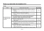
Страница 92: ...Refer to the Operating Instructions of the pan tilt head or the controller P 25 to 36 Cannot operate using the controller p Has the unit s power been turned on If the unit s power indicator LED is off it means that no power is being supplied to the unit P 16 p Is the unit connected to the pan tilt head and controller properly Has the power of the pan tilt head and controller been turned on Refer t...

Страница 93: ...Cannot operate the lens p Check that the unit and lens have been connected properly p Check that the iris selector switch on the lens is set to AUTO P 17 P 50 p Is the designated lens being used P 17 Cannot display the menus p Has OFF been set for the character output selection of the output connected to the monitor Check the character output selection Even if OFF is selected characters are displa...

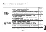
Страница 94: ...tion using a switcher or other unit with which the images are also switched when the camera to be operated is selected has the unit rather than another camera been selected p Has the video output been selected properly Check the video output format component output selection and other settings P 65 to 66 P 81 to 82 p Is the camera being used in conditions under which its use is prohibited Check th...

Страница 95: ...nlock function is being used by the composite video signal output Check that the horizontal phase and colour phase have been set correctly P 24 P 55 to 57 The pictures are too light or too dark p When the controller is being used Either set the iris to auto or set it to manual and adjust the iris manually P 37 to 46 p Check the connections and terminations of the video cables p Signal attenuation ...

Страница 96: ...s started p The cooling fan inside the unit has reached the end of its service life or it has failed If the camera would be kept using with displaying Fan Error it may cause malfunctioning Ask your dealer to replace it Fan Error is displayed in all video outputs regardless of the AWB ABB operation status display setting or character output selection To clear the Fan Error display display the menu ...

Страница 97: ... 96 E ENGLISH Appearance Unit mm AW HE870 HD Convertible Camera DEFINITION HIGH 83 171 104 5 12 9 77 34 10 17 5 ...

Страница 98: ...itched by menu RGB 1 0 V p p 75 j Dsub 50P M 1 SD format VIDEO OUT 1 0 V p p 75 j BNC M 1 Dsub 50P M 1 Continuous output Y C Y 1 0 V p p 75 j C 0 3 V p p 75 j burst Dsub 50P M 1 Y Pb Pr Y 1 0 V p p 75 j Pb Pr 0 525 V p p 75 j Dsub 50P M 1 Switched by menu RGB 1 0 V p p 75 j Dsub 50P M 1 Y C Y 1 0 V p p 75 j C 0 3 V p p 75 j burst Dsub 50P M 1 Standard illumination colour temperature 2 000 lx F10 3...

Страница 99: ... Hz Colour bars FULL Video output format setting 576i 720p 1080i Lens mount 2 3 bayonet mount Lens diaphragm Auto Manual manual available only when using the remote control Selectors MENU ENTER AWB AWB when menu screen is not displayed UP ABB ABB when menu screen is not displayed DOWN BAR BAR when menu screen is not displayed Input Output connectors VIDEO OUT BNC connector G L IN BNC connector IRI...

Страница 100: ...st be warmed up for at least 30 minutes if the temperature is 0 C or below Ambient operating humidity For storage 20 to 90 For guaranteeing operation 20 to 90 Dimensions W V H V D 83 M 104 5 M 192 mm excluding protrusions Mass Approx 1 2 kg Mass and dimensions indicated are approximate Specifications are subject to change without notice Specifications ...

Страница 101: ... 100 E ENGLISH Memo ...

Страница 102: ...sonal überlassen Hinweis Das Typenschild Seriennummerschild befindet sich an der Unterseite des Gerätes WARNUNG UM BRAND ODER STROMSCHLAGGEFAHR ZU REDUZIEREN DARF DIESES GERÄT WEDER REGEN NOCH NÄSSE AUSGESETZT WERDEN SETZEN SIE DAS GERÄT KEINEM TROPF ODER SPRITZWASSER AUS UND STELLEN SIE KEINE MIT FLÜSSIGKEITEN GEFÜLLTE GEGENSTÄNDE WIE Z B VASEN AUF DAS GERÄT VORSICHT NUR DAS EMPFOHLENE ZUBEHÖR VE...

Страница 103: ...d verhindert mögliche schädliche Auswirkungen auf Mensch und Umgebung die aus einer unsachgemäßen Handhabung von Abfall entstehen können Genauere Informationen zur nächstgelegenen Sammelstelle erhalten Sie bei Ihrer Gemeindeverwaltung In Übereinstimmung mit der Landesgesetzgebung können für die unsachgemäße Entsorgung dieser Art von Abfall Strafgebühren erhoben werden Für Geschäftskunden in der Eu...

Страница 104: ...omponenten Eingangsbuchse 22 wAnschluss einer Fernsteuerkonsole 23 wAnschluss mit Mehreren Kameras Zuführung der externen Synchronisiersignale 24 wAnschluss an den Innenraum Schwenk Neigekopf AW PH360 25 wAnschluss an den Innenraum Schwenk Neigekopf AW PH400 28 wAnschluss an den Innenraum Schwenk Neigekopf AW PH405 31 wAnschluss an den Freiluft Schwenk Neigekopf AW PH650 34 Bedienung des Systems 3...

Страница 105: ...Untermenü Modus Halogen Fluorescent Outdoor 60 wBeschreibung des Einstellungsbildschirms 61 Einstellen Ändern von Menüposten Modus User 68 wUntermenü Modus User 68 wBeschreibung des Einstellungsbildschirms 71 Ändern der Einstellungen 84 wÄndern der Formateinstellungen 84 wÄndern der Komponenteneinstellung 85 wEinstellen der EBU Matrix 86 Rückstellen auf die Anfangseinstellungen Werksvorgaben 87 wR...

Страница 106: ...pult oder einem Schwenk Neigekopf verbunden werden um eine dem Verwendungszweck entsprechende Systementwicklung zu ermöglichen p Der Einschub einer Optionskarte erschließt der Kamera weitere Einsatzmöglichkeiten p Um die Umwelt zu schützen wenn die konvertierbare HD Kamera am Ende ihrer Lebensdauer ausrangiert werden soll beauftragen Sie einen Fachbetrieb mit ihrer sachgerechten Entsorgung Hinweis...

Страница 107: ...Abbildung auf Computer Bildschirmen werden durch die Synchro Scan Funktion reduziert Zur Anpassung an den Verwendungszweck kann der optimale Zustand unter vier Betriebsmodi Halogen Fluorescent Outdoor und User ausgewählt werden Unterstützt die SDI Kartenoption 2 AW HHD870 Verwendet die gleichen Bedienungsverfahren wie die unserer konvertierbaren Kameras 3 Unsere Schwenk Neigeköpfe 4 und Steuerpult...

Страница 108: ... auf die Eigenschaften der CCD Bildsensoren zurückzuführen ist Bei Leuchtstofflampenlicht kann die ATW Funktion den Weißabgleich nachteilig beeinflussen p Im Inneren befindet sich ein Kühlgebläse Der Lüfter ist ein Verschleißteil Er sollte in der Regel 3 bis 5 Jahre nach der Installation ausgetauscht werden Falls der Ventilator versagt wird die Meldung Fan Error beim Einschalten der Stromversorgun...

Страница 109: ...äche des Objektivs oder des Prismas mit den Fingern berühren p Niemals Schleifkornreiniger für das Reinigen des Kameragehäuses verwenden p Die Kamera niemals gegen die Sonne richten unabhängig davon ob die Kamera eingeschaltet ist oder nicht p Setzen Sie die Kamera oder andere Geräte weder Regen noch Nässe aus und versuchen Sie nicht die Ausrüstung bei nassen Bedingungen zu benutzen Die Kamera nic...

Страница 110: ...rtnäckig anhaftender Schmutz ist durch vorsichtiges Reiben mit einem milden Reinigungsmittel zu entfernen p Vorsicht ist bei der Handhabung der Kamera in der Nähe von Punktleuchten oder anderen hellen Lichtquellen bzw bei reflektierenden Objekten oder Oberflächen geboten p Ergreifen Sie sofortige Schutzmaßnahmen falls die Kamera jemals nass werden sollte Schalten Sie die Kamera aus und lassen Sie ...

Страница 111: ...t p Orte in der Nähe des Luftauslasses einer Klimaanlage oder einer Tür wo die Kamera einem durchziehenden Außenluftstrom ausgesetzt ist oder andere Orte wo die Temperatur plötzlichen Änderungen unterliegt da solche Orte zu Beschlagen des Objektivbereichs und oder Kondensationsbildung führen können p Orte die beträchtlichen Vibrationen ausgesetzt sind wie z B auf einem Auto p Orte mit hohem Anteil...

Страница 112: ...e den Fallschutzdraht an der Kameramontagegewindebohrung Zollschraube Befestigungsschraube für Draht mitgeliefert Zollschraube 1 4 20UNC Fallschutzdraht Federscheibe mitgeliefert Befestigungsschrauben Zollschrauben 1 4 20UNC Schwenk Neigekopf oder Kamerahaltebügel Unterlegscheiben Federscheiben Unterlegscheibe mitgeliefert Anziehen der Befestigungsschrauben Verwenden Sie die in der nachstehenden T...

Страница 113: ...n Zollschrauben 1 4 20UNC 2 Zur Montage der Kamera Ermitteln Sie die Länge dieser Schrauben indem Sie die Dicke des Kamerahaltebügels berücksichtigen Befestigungsschrauben M6 für die Installation des Fallschutzdrahtes Verwenden Sie am Installationsort unbedingt die Ankerschrauben und vergewissern Sie sich dass die Festigkeit der Installationsfläche mindestens dem Zehnfachen des Gesamtgewichts alle...

Страница 114: ...nen wVorderseite Draufsicht Rückseite Unterseite Vorderseite Draufsicht Unterseite 32 mm 20 mm 10 mm 18 mm Rückseite 20 mm 32 mm Befestigungsschrauben Zollschrauben 1 4 20UNC Tiefe 10 mm Befestigungsschrauben Zollschrauben 1 4 20UNC Tiefe 10 mm 17 5 mm ...

Страница 115: ...tens 3 Sekunden lang gedrückt wird Der Menübildschirm wird abgeschaltet wenn die Taste bei angezeigtem Menü mindestens 3 Sekunden lang gedrückt wird Wird diese Taste gedrückt während ein Posten auf einem Untermenübildschirm geändert wird werden die Einstellwerte auf die Werte vor der Änderung zurückgesetzt Eingabe Weißabgleichautomatiktaste ENTER AWB Wird diese Taste auf dem Hauptmenübildschirm ge...

Страница 116: ...bildschirm im veränderbaren Zustand befindet wird der Wert erniedrigt Wird das Menü nicht angezeigt werden der Farbbalken und die Aufnahmebedingungen durch Drücken der Taste etwa 2 Sekunden lang angezeigt Video Ausgangsbuchse VIDEO OUT Ein Composite Videosignal liegt an dieser Buchse an 1 V s s 75 j BNC Buchse Blendenanschluss IRIS Schließen Sie das Blendenkabel des motorgetriebenen Objektivs z B ...

Страница 117: ...Verwenden Sie unbedingt das mit der Haupteinheit gelieferte Gleichstromkabel Hinweis Kabelbride Dient der Sicherung des an die 12 V Gleichstrom Eingangsbuchse angeschlossenen Gleichstromkabels mit ø5 5 mm Stecker um Herausrutschen zu verhüten Sichern Sie das Gleichstromkabel unbedingt mit der Kabelklemme G L Eingangssteckverbinder G L IN Externe Synchronisiersignale BB sind diesem Steckverbinder z...

Страница 118: ...ist Hinweise p Verwenden Sie das IRIS Kabel AW CA12T12A wenn Ihr Objektivkabel zu kurz ist 1 Drehen Sie den Knopf des Objektivbefestigungsringes gegen den Uhrzeigersinn und nehmen Sie die Objektivfassungskappe ab 2 Bringen Sie das Objektiv an der Kamera an und drehen Sie den Knopf des Objktivbefestigungsringes im Uhrzeigersinn um das Objektiv sicher zu befestigen 3 Das IRIS Kabel an den IRIS Steck...

Страница 119: ...ben selbst Kameramontagegewindebohrungen Zollschrauben 1 4 20UNC Tiefe 10 mm Kamera Montageadapter Verhütung von Herunterfallen oder Lösen der Kamera p Wenn Sie eine Kamera an den Schwenk Kippkopf AW PH360 AW PH400 AW PH405 und AW PH650 montieren folgen Sie den Anweisungen in der Bedienungsanleitung um eine einwandfreie Befestigung der Kamera zu gewährleisten Sichern Sie die Kamera zusätzlich mit ...

Страница 120: ...Objektiv und Kabeln 8 kg nicht überschreitet p Achten Sie darauf dass ein Fallschutzdraht so angebracht wird dass die Falldistanz 150 mm nicht überschreitet p Ziehen Sie die Befestigungsschrauben mit den in der nachstehenden Tabelle angegebenen Anzugswerten fest und prüfen Sie dann ob Spiel oder Wackeligkeit vorhanden ist Schrauben Anzugsmoment Befestigungsschrauben Zollschrauben 2 0 N m 20 kgf cm...

Страница 121: ...orden ist muss unbedingt die Stativschraube oder ein anderes derartiges Befestigungselement verwendet werden um Herunterfallen der Kamera zu verhüten p Wird die Kamera an einer Fläche über der Kamera montiert dürfen die Belüftungsöffnungen des Lüfters nicht blockiert werden p Achten Sie darauf dass das Gesamtgewicht von Haltebügel Kamera Objektiv und Kabeln 8 kg nicht überschreitet p Achten Sie da...

Страница 122: ...pezifikationen der Kameramontagegewindebohrungen siehe Wichtige Bedienungselemente und ihre Funktionen auf Seite 13 p Wenn Sie die Kameramontagegewindebohrungen auf der Oberseite der Kamera verwenden bei Aufhängung der Kamera achten Sie darauf dass die Belüftungsöffnungen des Ventilators nicht blockiert werden p Wenn Sie die Kameramontagegewindebohrungen auf der Oberseite der Kamera verwenden bei ...

Страница 123: ...t zu verbinden das mit HD SD Komponentensignal Eingangsbuchsen ausgestattet ist p Composite Signale von der Buchse VIDEO OUT und Komponentensignale vom Steckverbinder I F REMOTE können gleichzeitig ausgegeben werden p Verwenden Sie das mit dem Modell AW HE870 gelieferte Gleichstromkabel mit ø5 5 mm Stecker für den Anschluss an die 12 V Eingangsbuchse Netzgerät AW PS505A Buchse VIDEO OUT 75 j Koaxi...

Страница 124: ...r AW CA50T8 oder AW CA50T9 RS 422 RS 232C Konverter mit dem Anschluss I F REMOTE der Kamera p Die Entfernung zwischen der FSK und dem AW CA50T8 oder AW CA50T9 RS 422 RS 232C Konverter kann mit einem 10BASE T Straight Kabel entsprechend UTP Kategorie 5 auf ein Maximum von etwa 1 000 m verlängert werden Zoomobjektiv Blendensteuerung Mit AW HE870 geliefertes Gleichstromkabel Netzgerät AW PS505A Netzg...

Страница 125: ...er Video Ausgang An den Spezialeffektgenerator oder das Überwachungssystem p Dreiwertige Synchronisiersignale des HD Formats werden nicht unterstützt p Bei Verwendung von externer Synchronisierung wird nur das Ausgangssignal für das gewählte Video Ausgabeformat Format synchronisiert 1080i 720p oder 576i Bei Wahl eines HD Formats 1080i oder 720p wird weder das VIDEO OUT Signal FBAS Signal noch das ...

Страница 126: ...ndet werden p Verbinden Sie die Buchsen CONTROL OUT TO PAN TILT HEAD P1 bis P5 des AW RP400 und die Buchse RP des AW PH360 über ein 10BASE T Straight Kabel wenn das Schwenk Neigesteuerpult AW RP400 verwendet wird Die maximale Entfernung beträgt 500 m wenn Kabel der UTP Kategorie 5 oder entsprechende Kabel verwendet werden p Verwenden Sie das mit dem Schwenk Neigekopf gelieferte Kamerakabel um den ...

Страница 127: ... nicht vom AW PH360 ausgegeben werden p Einzelheiten bezüglich der internen Schaltereinstellungen usw des Schwenk Neigekopfes entnehmen Sie bitte der Bedienungsanleitung des AW PH360 p Verwenden Sie das Objektiv AW LZ17MD9AG wenn die Kamera auf den Schwenk Neigekopf AW PH360 montiert wird Andere Objektive als AW LZ17MD9AG können nicht verwendet werden Montieren Sie die Kamera nicht auf den AW PH36...

Страница 128: ...ennquerschnitt 1 25 mm2 oder mehr Schwenk Neigesteuerpult AW RP400 Fernsteuerkonsole AW CB400 Multifunktions Steuergerät AW RP655 Multi Hybrid Steuerpult AW RP555 Schwenk Neigekopf Kamera Steuersignale 10BASE T Geradkabael Monitor Netzgerät AW PS505A Netzgerät AW PS505A Netzgerät AW PS505A Wenn eine SDI Karte AW HHD870 installiert worden ist Monitor Y Pr Pb SD Komponenten signal Die SDI Buchse hat...

Страница 129: ...hse PAN TILT HEAD des Protokollkonverters AW IF400 und die Buchse RP des AW PH400 über ein 10BASE T Straight Kabel Die maximale Entfernung beträgt 500 m wenn Kabel der UTP Kategorie 5 oder entsprechende Kabel verwendet werden p Verbinden Sie die Buchsen CONTROL OUT TO PAN TILT HEAD P1 bis P5 des AW RP400 und die Buchse RP des Schwenk Neigekopfes über ein 10BASE T Straight Kabel wenn das Schwenk Ne...

Страница 130: ... PH400 zu verbinden p Verwenden Sie ein Koaxialkabel um die Buchse SDI des Modells AW PH400 mit der SDI Eingangsbuchse des Farbmonitors zu verbinden p Analoge HD Komponentensignale 1080i oder 720p können nicht vom AW PH400 ausgegeben werden Hinweis p AW IF400 Schalterstellungen wenn AW RP555 AW RP655 verwendet wird SW1 SW2 SET UP 1 2 3 Tilt range 4 OFF OFF ON OFF ON 300 Grad OFF 190 Grad OFF Syste...

Страница 131: ... SDI Composite Signal Monitor Protokollkonverter AW IF400 Schwenk Neigesteuerpult AW RP400 Fernsteuerkonsole AW CB400 Multifunktions Steuergerät AW RP655 Multi Hybrid Steuerpult AW RP555 Schwenk Neigekopf Kamera Steuersignale 10BASE T Geradkabel Netzgerät AW PS505A Monitor Netzgerät AW PS505A Netzgerät AW PS505A Netzgerät AW PS505A Mit AW PH400 geliefertes Netzkabel Zum Anschluss LENS I F 1 Blende...

Страница 132: ...OUT TO PAN TILT HEAD P1 bis P5 des AW RP400 und die Buchse CONTROLLER des Protokollkonverters AW IF400 über ein 10BASE T Straight Kabel wenn das Schwenk Neigesteuerpult AW RP400 verwendet wird Die maximale Entfernung beträgt 500 m wenn Kabel der UTP Kategorie 5 oder entsprechende Kabel verwendet werden Verbinden Sie die Buchse PAN TILT HEAD des Protokollkonverters AW IF400 und die Buchse RP des AW...

Страница 133: ...alkabel um die Buchse SDI des Modells AW PH405 mit der SDI Eingangsbuchse des Farbmonitors zu verbinden p Wenn analoge HD Komponentensignale 1080i oder 720p übertragen werden muss der Schalter in der Haupteinheit AW PH405 auf die Position HD gestellt werden die Kabelkompensationsschaltung wird umgangen Konsultieren Sie Ihren Händler Hinweis p AW IF400 Schalterstellungen wenn AW RP400 verwendet wir...

Страница 134: ...bel Protokollkonverter AW IF400 Schwenk Neigesteuerpult AW RP400 Fernsteuerkonsole AW CB400 Multifunktions Steuergerät AW RP655 Multi Hybrid Steuerpult AW RP555 Schwenk Neigekopf Kamera Steuersignale 10BASE T Geradkabel Netzgerät AW PS505A Monitor Netzgerät AW PS505A Netzgerät AW PS505A Netzgerät AW PS505A Blendensteuer kabel Wenn eine SDI Karte AW HHD870 installiert worden ist Zoom Fokus Steuerka...

Страница 135: ...NTROL OUT TO PAN TILT HEAD P1 bis P5 des AW RP400 und die Buchse CONTROLLER des Protokollkonverters AW IF400 über ein 10BASE T Straight Kabel wenn das Schwenk Neigesteuerpult AW RP400 verwendet wird Die maximale Entfernung beträgt 500 m wenn Kabel der UTP Kategorie 5 oder entsprechende Kabel verwendet werden Verbinden Sie die Buchse PAN TILT HEAD des Protokollkonverters AW IF400 und die Buchse RP ...

Страница 136: ...ors zu verbinden p Wenn analoge HD Komponentensignale 1080i oder 720p übertragen werden stellen Sie SW2 und SW3 an der COMP Platine auf die Position HD Die Kabelkompensationsschaltung wird nicht aktiviert selbst wenn SW1 zu diesem Zeitpunkt auf ON gestellt wird Stellen Sie daher diesen Schalter auf OFF p Schlagen Sie bezüglich der Anschlüsse im Gehäuse und für andere Einzelheiten in der Bedienungs...

Страница 137: ...polig RJ 45 Kupplung Protokollkonverter AW IF400 Schwenk Neigesteuerpult AW RP400 Fernsteuerkonsole AW CB400 Multifunktions Steuergerät AW RP655 Multi Hybrid Steuerpult AW RP555 Schwenk Neigekopf Kamera Steuersignale 10BASE T Geradkabel Netzgerät AW PS505A Monitor Netzgerät AW PS505A Netzgerät AW PS505A Netzgerät AW PS505A Pb Y MULTI SDI OUT POWER Wenn eine SDI Karte AW HHD870 installiert worden i...

Страница 138: ...nsgeschwindigkeit des Knopfes IRIS gewählt worden ist Zum Umschalten zwischen DTL ON und OFF Bei Einstellung auf ON kann die Wahl LOW HIGH auf dem LCD Menü durchgeführt werden Zur Wahl von GAIN 0dB L M H oder AGC Die gewählte Taste leuchtet auf 2 Die Tasten L M H können in Schritten von 1 dB zwischen 0 dB und 18 dB auf dem LCD des Modells CB400 eingestellt werden 3 11 Außerdem kann die Einstellung...

Страница 139: ...tion unterbrochen wird weil z B der Schalter OPERATE auf OFF gestellt CAMERA SELECT umgeschaltet oder das Kommunikationskabel abgetrennt worden ist 6 Die Lampe der Taste ABB oder AWB blinkt während der Ausführung des automatischen Weiß bzw Schwarzabgleichs Wird ABB oder AWB erfolgreich abgeschlossen erlischt die entsprechende Lampe anderenfalls leuchtet sie auf 7 Die Taste leuchtet auf ohne dass A...

Страница 140: ...n zu rollen Drücken Sie die Taste D von OPTION SW um die Postenliste nach unten zu rollen Drücken Sie die Taste B von OPTION SW um die Postenwahl zu bestätigen Nachdem Sie einen Posten ausgewählt haben ändern Sie den Einstellwert des Modells AW HE870 Drücken Sie die Taste C von OPTION SW um den Einstellwert in positiver Richtung zu ändern und die Taste D von OPTION SW um den Einstellwert in negati...

Страница 141: ...ie Verstärkung Die Taste GAIN leuchtet wenn die Einstellung AUTO gewählt wird Blinkt wenn ein Alarm Fan Error von der Kamera empfangen wird 4 Jograd Rechts Wenn sich das LCD Display im Verstärkungs Einstellmodus befindet Stellen Sie den Posten B GAIN ein 150 bis 150 Wenn sich das LCD Display im Schwarzwert Einstellmodus befindet Stellen Sie den Posten B PEDESTAL ein 150 bis 150 7 Wenn das Kamerame...

Страница 142: ...nn die Kommunikation unterbrochen wird weil z B der Schalter OPERATE auf OFF gestellt CAMERA SELECT umgeschaltet oder das Kommunikationskabel abgetrennt worden ist 5 Die Taste leuchtet auf ohne dass ABB ausgeführt wird wenn der Farbbalken angezeigt wird 6 SCENE FILE CAM BAR und GAINUP des jeweiligen SCENE Postens sowie die Zustände von W B MODE R B GAIN und T R B PED werden synchronisiert 7 Bei Wa...

Страница 143: ... wird ohne den Schwenk Neigekopf zu benutzen Verfahren für Kameramenüoperationen AW RP655 Drücken Sie die Taste MENU um das LCD Display in den Menümodus zu versetzen Drehen Sie das Jograd Haupt zur Wahl von CAMERA SETTING Drücken Sie die Taste OK Die Anzeige des Auswahlmenüs SCENE erscheint auf dem LCD Feld SCENE HALOGEN OK Key Wählen Sie die bevorzugte Szene aus und drücken Sie die Taste OK Die r...

Страница 144: ... ändern es ist nicht möglich die Dateneinstellung über den Einstellbereich der Daten hinaus zu ändern Drücken Sie das Jograd Haupt nieder um die Einstellungen einzugeben Um das Kameramenü zu verlassen drücken Sie die Taste MENU oder die Taste R B GAIN PED p Wenn das Modell AW HE870 gesteuert wird wird G L SETTING nicht angezeigt Der Posten G L muss mit dem Kameramenü des Modells AW HE870 eingestel...

Страница 145: ...Die Taste SHUTTER leuchtet in allen Modi außer Verschluss AUS auf Die unter den Tasten PRESET gespeicherten Verschlussmodus Einstellungen sind wie folgt MODE PRESET Nr MODE PRESET Nr 1 120 PRESET1 1 4000 PRESET6 1 250 PRESET2 1 10000 PRESET7 1 500 PRESET3 SYNCHRO SCAN PRESET8 1 1000 PRESET4 ELC PRESET9 1 2000 PRESET5 OFF PRESET10 Zum Umschalten der SCENE Datei User Halogen Fluorescent Outdoor Benu...

Страница 146: ...n ausgeführt wird wenn der Weißabgleichmodus der Haupteinheit auf ATW PRESET 3200K oder PRESET 5600K eingestellt oder der Farbbalken angezeigt wird 3 Das Blinken hört auf wenn die Kommunikation unterbrochen wird weil z B der Schalter OPERATE auf OFF gestellt CAMERA SELECT umgeschaltet oder das Kommunikationskabel abgetrennt worden ist 4 Die Taste leuchtet auf ohne dass ABB ausgeführt wird wenn der...

Страница 147: ...es Modells AW HE870 wird auf dem Monitor angezeigt Wählen Sie einen Menüposten aus Drücken Sie die Taste YES um die Postenliste nach unten zu rollen Drücken Sie die Taste NO um die Postenliste nach oben zu rollen Drücken Sie die Taste ITEM um die Postenwahl zu bestätigen Nachdem Sie einen Posten ausgewählt haben ändern Sie den Einstellwert des Modells AW HE870 Drücken Sie die Taste YES um den Eins...

Страница 148: ...hmen z B bei Hochzeiten Partys Vorlesungen Veranstaltungen usw Die Einstellungen können mithilfe eines einfachen Menüs geändert werden q Modus Fluorescent Leuchtstofflampen Dieser Modus eignet sich für Innenaufnahmen unter Leuchtstofflampenlicht Die Einstellungen können mithilfe eines einfachen Menüs geändert werden q Modus Outdoor Außenaufnahme Dieser Modus eignet sich für Außenaufnahmen Die Eins...

Страница 149: ...ste UP ABB oder DOWN BAR Bewegen Sie den Cursor zum gewünschten Betriebsmodus 3 Drücken Sie die Taste ENTER AWB Der ausgewählte Betriebsmodus wird wirksam Nachdem das Betriebsmodus Einstellungsmenü für etwa fünf Sekunden angezeigt wurde kehrt die Kamera auf die Betriebsbereitschaft zurück Danach arbeitet die Kamera in dem gewählten Betriebsmodus Taste MENU Taste ENTER AWB Taste UP ABB Taste DOWN B...

Страница 150: ...er Weißabgleich einmal eingestellt worden ist braucht er nicht wieder eingestellt zu werden sofern die Kamera unter denselben Bedingungen benutzt werden soll 6 Stellen Sie den Schwarzabgleich ein p Der Schwarzabgleich muss eingestellt werden wenn die Kamera zum ersten Mal und nach längerer Nichtbenutzung wieder benutzt wird p Er muss ebenfalls eingestellt werden wenn sich die Umgebungstemperatur b...

Страница 151: ...ng ein um die optimale Schärfe innerhalb des Zoombereichs zu erhalten Ziehen Sie den Auflagemaß Feststellknopf nach Abschluss der Fokussierung fest wBlendenverstärkungsregelung in einem Objektiv p An der Vorderseite eines Objektivs befindet sich normalerweise eine Blendenverstärkungsregelungsöffnung G S Die Einstellung der Blendenverstärkung mithilfe eines Schraubenziehers durch diese Öffnung kann...

Страница 152: ...Bedingungen werden erneuert sobald Sie neue Bedingungen eingeben 1 Wählen Sie entweder AWB A oder AWB B für den Weißabgleichmodus 2 Die Kamera auf ein weißes Objekt richten eine weiße Wand oder ein weißes Taschentuch und einzoomen um die Abbildung möglichst weit zu vergrößern Richten Sie die Kamera für die Weißabgleich Einstellung auf ein weißes Objekt und versuchen Sie dieses in der Mitte des Mon...

Страница 153: ...ht richtig wenn ein sehr helles Licht z B Leuchtstofflampe auf einen Bildschirm scheint p Der Weißabgleich wird eventuell nicht genau eingestellt wenn die aufzunehmende Szene kein weißes Objekt enthält Hinweise q Manuelle Weißabgleich Einstellung Manuelle Einstellung ist nur im Anwendermodus möglich 1 Stellen Sie den Weißabgleichmodus im Menü entweder auf AWB A oder AWB B ein 2 Richten Sie die Kam...

Страница 154: ...rd nach der Schwarzabgleich Einstellung automatisch auf 0 zurückgestellt Gemälde Einstellung nur im Modus User Wird die Taste UP ABB länger als 2 Sekunden gedrückt gehalten erfolgt der Schwarzabgleich in 30 Sekunden Im Modus User kann eine Schwarzabgleich Feineinstellung durch Ändern der Einstellung des Postens R pedestal B pedestal mit dem Posten Painting des Untermenüs Colour Set nach der Schwar...

Страница 155: ...as Bitte wenden Sie sich für die Einstellung an Ihren Händler 1 Das Objektiv schließen 2 Wählen Sie den Posten Pedestal im Untermenü Brightness Set 3 Stellen Sie den Schwarzabhebungspegel mit der Taste UP ABB oder der Taste DOWN BAR auf 0 035 V ein Taste UP ABB Taste DOWN BAR Brightness Set A Iris Level 0 A Iris PEAK AVG 0 A Iris Area Top Cut Shutter Mode Step Step Synchro Off Gain 0dB AGC Max Gai...

Страница 156: ...ramenü an Hinweise p Wenn die Horizontalphaseneinstellung verschoben wird wird die Farbphase ebenfalls verschoben Stellen Sie die Farbphase immer dann ein wenn die Horizontalphaseneinstellung verschoben wird p Die Phasen der Composite und Y C Signale werden für die Einstellungen verriegelt p Dreiwertige Synchronisiersignale des HD Formats werden nicht unterstützt p Bei Verwendung von externer Sync...

Страница 157: ...OWN BAR Schalter für mindestens 2 Sekunden drücken um den Farbbalken anzuzeigen Halten Sie die Taste MENU 3 Sekunden oder länger gedrückt um das Hauptmenü anzuzeigen Drücken Sie die Taste UP ABB oder DOWN BAR um den Cursor nach G L Set zu bewegen und drücken Sie dann die Taste ENTER AWB um das Untermenü G L Set anzuzeigen Wählen Sie H Phase im Untermenü G L Set Die Horizontalphase mit dem UP ABB S...

Страница 158: ...r für mindestens 2 Sekunden drücken um den Farbbalken anzuzeigen Halten Sie die Taste MENU 3 Sekunden oder länger gedrückt um das Hauptmenü anzuzeigen Drücken Sie die Taste UP ABB oder DOWN BAR um den Cursor nach G L Set zu bewegen und drücken Sie dann die Taste ENTER AWB um das Untermenü G L Set anzuzeigen Wählen Sie SC Coarse im Untermenü G L Set Die Grobeinstellung mit dem UP ABB Schalter und d...

Страница 159: ...zeigten Zeichen können je nach dem verwendeten Monitor abgeschnitten werden Hinweise q Einstellung bei unabhängigem Einsatz der Kamera 1 Halten Sie die Taste MENU 3 Sekunden oder länger gedrückt um das Hauptmenü des jeweiligen Betriebsmodus aufzurufen Angaben zur Wahl des Betriebsmodus finden Sie auf Seite 47 2 Bei jedem Drücken der Taste UP ABB oder DOWN BAR wird der ausgewählte Posten nach oben ...

Страница 160: ...N BAR q Hauptmenüanzeige Hauptmenü des Modus Halogen Fluorescent Outdoor Halogen Mode Set Brightness Set Colour Set Detail Set G L Set Other Set 1 Other Set 2 Initialize Data Zeigt den Betriebsmodus an Hauptmenü des Modus User User Mode Set Brightness Set Colour Set HD Detail Set SD Detail Set Colour Matrix Set Colour Correction Set G L Set Other Set 1 Other Set 2 Initialize Data Zeigt den Betrieb...

Страница 161: ... 0 White Bal AWB A ATW Speed Return Seite Colour Set Detail Set DTL Select Normal Level High Noise Suppress Off Clean DNR Off Flesh Noise Sup Off Return Seite Detail Set G L Set H Phase 0 SC Coarse 90deg SC Fine 0 H Phase SC Fine Step 1 Return Seite G L Set Other Set 1 Contrast Gamma Mid SD 2D LPF Off Return Seite Other Set Other Set 2 Format 1080i Downconv Mode Squeeze Component Y Pb Pr Status Of...

Страница 162: ... der Mitte gemessen wobei jeweils ein Drittel der Bildschirmfläche von oben und unten sowie von rechts und links von der Messung ausgeschlossen wird Top Cut Etwa ein Drittel des oberen Bildschirmteils wird von der Messung ausgeschlossen BTM Cut Etwa ein Drittel des unteren Bildschirmteils wird von der Messung ausgeschlossen R L Cut Etwa ein Drittel des linken und rechten Bildschirmteils wird von d...

Страница 163: ...as Flimmern unter Leuchtstoffröhren Beleuchtung zunehmen Hinweise Verstärkungs Einstellung Gain Auto 6 dB bis 18 dB Auto Die Lichtmenge wird automatisch eingestellt 6 dB bis 1 dB Diese Einstellung ermöglicht Aufnahmen mit optimaler Verstärkungseinstellung unter Bedingungen mit großer Lichtmenge Wenn sie benutzt wird können Bilder mit minimalem Rauschen aufgenommen werden aber der Dynamikbereich wi...

Страница 164: ...osition eingestellt Der Weißabgleich wird über einen ungefähren Farbtemperaturbereich von 2000K bis 10000K nachgeführt AWB A AWB B Wenn der Weißabgleich einmal eingestellt worden ist erübrigt sich eine erneute Einstellung bei einfacher Wahl von AWB A oder AWB B vorausgesetzt dass die Kamera unter den gleichen Bedingungen benutzt wird 3200K Der Weißabgleich wird auf einen Wert von 3200K eingestellt...

Страница 165: ...gel eingestellt werden Einstellung des Rauschunterdrückungspegels Noise Suppress Off Low High Das Bildschirmrauschen kann reduziert werden wenn der Detailpegel auf High oder Low gestellt ist Clean DNR Einstellung Clean DNR Off Low High Der von der Clean DNR Funktion erzeugte Rauschunterdrückungseffekt kann gewählt werden Einstellung des Hautfarben Rauschstörungs Unterdrückungspegels Flesh Noise Su...

Страница 166: ...onisierungssignal zugeführt wird Gültig für die Composite und Y C Signale des SD Formats Feineinstellung der Horizontalphase und Farbphase H Phase SC Fine Step 1 bis 10 Die Stufe der Horizontalphasen Einstellung und Farbphasen Feineinstellung kann gleichzeitig gewählt werden Other Set Kontrasteinstellung Contrast Gamma Low Mid High Der Kontrast kann auf einen von drei Pegeln eingestellt werden SD ...

Страница 167: ...tellung auf Seite 85 Wahl von Ein Aus der Anzeige des AWB ABB Betriebszustands Status Off On Werkseinstellung Off Mit diesem Posten wird die Anzeige des Betriebszustands für AWB automatischer Weißabgleich oder ABB automatischer Schwarzabgleich auf ON oder OFF gesetzt Wenn AWB oder ABB ausgeführt wird während dieser Posten auf On eingestellt ist erscheint die folgende Anzeige AWB ACTIVE Diese Anzei...

Страница 168: ...eingestellt werden konnte wird mit RGB angezeigt Wahl der Zeichenausgabe Character Mix Component Off On Composite Off On Option Off On Diese Option dient der Wahl wie Kameramenü Status und andere Zeichen auszugeben sind Aus oder Ein Component Dient der Wahl wie die Zeichen der Komponentensignale RGB Y Pb Pr auszugeben sind Composite Dient der Wahl der Zeichen Ausgabemethode für FBAS Signale und Y ...

Страница 169: ... Detail 0 Return 0 1 2 3 4 5 6 Seite HD Detail Set HD Detail Set 2 2 Chroma Detail 0 Clean DNR Off Flesh Noise Sup Off Precision Detail Off Return 7 8 9 Brightness Set A Iris Level 0 A Iris PEAK AVG 0 A Iris Area Top Cut Shutter Mode Step Step Synchro Off Gain 0dB AGC Max Gain Pedestal 0 Return Seite Brightness Set Colour Set Chroma Level 2 White Bal AWB A ATW Speed Painting R Gain 0 B Gain 0 R Pe...

Страница 170: ... Correction 3 3 G_Cy Gain 0 G_Cy Phase 0 Cy Gain 44 Cy Phase 15 Cy_B Gain 0 Cy_B Phase 0 B Gain 20 B Phase 36 Return SD Detail Set 1 2 Detail High H Detail Level H 16 V Detail Level H 3 H Detail Level L 13 V Detail Level L 2 Detail Band 4 Noise Suppress 3 Level Dependent 10 Dark Detail 0 Return A B C Seite SD Detail Set SD Detail Set 2 2 Chroma Detail 0 Clean DNR Off Flesh Noise Sup Off Return D E...

Страница 171: ... Seite Other Set Other Set 2 Format 1080i Downconv Mode Squeeze Component Y Pb Pr Status Off Character Mix Component On Composite On Option On Return R S T U V G L Set H Phase 0 SC Coarse 90deg SC Fine 0 H Phase SC Fine Step 1 Return G H I J Seite G L Set p Um an die anfänglichen Einstellungen zurückzukehren siehe Seite 87 Einstellen Ändern von Menüposten Modus User ...

Страница 172: ... der Mitte gemessen wobei jeweils ein Drittel der Bildschirmfläche von oben und unten sowie von rechts und links von der Messung ausgeschlossen wird Top Cut Etwa ein Drittel des oberen Bildschirmteils wird von der Messung ausgeschlossen BTM Cut Etwa ein Drittel des unteren Bildschirmteils wird von der Messung ausgeschlossen R L Cut Etwa ein Drittel des linken und rechten Bildschirmteils wird von d...

Страница 173: ...i ELC kann das Flimmern unter Leuchtstoffröhren Beleuchtung zunehmen Hinweise Verstärkungs Einstellung Gain Auto 6 dB bis 18 dB Auto Die Lichtmenge wird automatisch eingestellt 6 dB bis 1 dB Diese Einstellung ermöglicht Aufnahmen mit optimaler Verstärkungseinstellung unter Bedingungen mit großer Lichtmenge Wenn sie benutzt wird können Bilder mit minimalem Rauschen aufgenommen werden aber der Dynam...

Страница 174: ...ung kann nach der AWB Einstellung mit R Verstärkung und B Verstärkung für die Maleinstellung durchgeführt werden 3200K Der Weißabgleich wird auf einen Wert von 3200K eingestellt 5600K Der Weißabgleich wird auf einen Wert von 5600K eingestellt ATW Geschwindigkeitseinstellung ATW Speed Slow2 Slow1 Mid Fast1 Fast2 Die ATW Geschwindigkeit kann eingestellt werden Gemäldeeinstellung Painting R Gain B Ga...

Страница 175: ...High ungeachtet der Richtung H oder V mindestens eine Position höher als bei Low sein 3Einstellung des Detailbands Detail Band 1 bis 5 Das Konturkorrekturband kann bei auf High oder Low eingestelltem Detailpegel eingestellt werden Je höher die Einstellung um so feiner die Details 4Einstellung des Rauschunterdrückungspegels Noise Suppress 1 bis 10 Das Bildschirmrauschen kann bei auf High oder Low g...

Страница 176: ... der Clean DNR Funktion erzeugte Rauschunterdrückungseffekt kann gewählt werden 9Einstellung des Hautfarben Rauschstörungs Unterdrückungspegels Flesh Noise Sup Off Low High Die Hautfarben Rauschstörungen werden in zwei Schritten unterdrückt wenn der Detailpegel auf High oder Low gestellt ist Einstellung des Präzisionsdetailpegels Precision Detail Off Low High Mit dieser Einstellung wird die Detail...

Страница 177: ... ungeachtet der Richtung H oder V mindestens eine Position höher als bei Low sein Einstellung des Detailbands Detail Band 1 bis 5 Das Konturkorrekturband kann bei auf High oder Low eingestelltem Detailpegel eingestellt werden Je höher die Einstellung um so feiner die Details AEinstellung des Rauschunterdrückungspegels Noise Suppress 1 bis 10 Das Bildschirmrauschen kann bei auf High oder Low gestel...

Страница 178: ...pegels Chroma Detail 0 bis 15 Die Kontur der farbreichen Teile eines Objektes kann betont werden EClean DNR Einstellung Clean DNR Off Low High Der von der Clean DNR Funktion erzeugte Rauschunterdrückungseffekt kann gewählt werden FEinstellung des Hautfarben Rauschstörungs Unterdrückungspegels Flesh Noise Sup Off Low High Die Hautfarben Rauschstörungen werden in zwei Schritten unterdrückt wenn der ...

Страница 179: ...e in Richtung der R B Achse Linear Matrix G R Matrix G R 31 bis 31 Dieser Posten dient der Einstellung der Farbe in Richtung der G R Achse Linear Matrix G B Matrix G B 31 bis 31 Dieser Posten dient der Einstellung der Farbe in Richtung der G B Achse Linear Matrix B G Matrix B G 31 bis 31 Dieser Posten dient der Einstellung der Farbe in Richtung der B G Achse Linear Matrix B R Matrix B R 31 bis 31 ...

Страница 180: ... Gain 127 bis 127 Verstärkt oder verringert Gelb Yl Phase 127 bis 127 Variiert den Farbton von Gelb Yl_G Gain 127 bis 127 Erhöht oder verringert die Zwischenfarbe zwischen Gelb und Grün Yl_G Phase 127 bis 127 Variiert den Farbton der Zwischenfarbe zwischen Gelb und Grün G Gain 127 bis 127 Verstärkt oder verringert Grün G Phase 127 bis 127 Variiert den Farbton von Grün G_Cy Gain 127 bis 127 Erhöht ...

Страница 181: ...ase H Phase SC Fine Step 1 bis 10 Die Stufe der Horizontalphasen Einstellung und Farbphasen Feineinstellung kann gleichzeitig gewählt werden Other Set KEinstellung des Gammakorrekturpegels Gamma 0 35 bis 0 55 Der Gammakorrekturpegel kann eingestellt werden LEinstellung des Kniekompensationspegels Knee Point 88 bis 98 Dynamic 88 bis 98 Der Pegel der Videosignale die der Kniekompensation Kniepunkt u...

Страница 182: ...ormats QEBU Matrixeinstellung EBU Matrix Set Off On Off Dadurch werden die Einstellungen von Farbmatrix Farbkorrektur und Einstellung des Chromapegels auf die jeweiligen Pegel vor der EBU Matrixeinstellung zurückgesetzt On Diese Option ermöglicht die Wahl der EBU Matrixeinstellung für die Posten von Farbmatrix Chromapegel Einstellung und Farbkorrektur Siehe Einstellen der EBU Matrix auf Seite 86 R...

Страница 183: ...tands Status Off On Werkseinstellung Off Mit diesem Posten wird die Anzeige des Betriebszustands für AWB automatischer Weißabgleich oder ABB automatischer Schwarzabgleich auf ON oder OFF gesetzt Wenn AWB oder ABB ausgeführt wird während dieser Posten auf On eingestellt ist erscheint die folgende Anzeige AWB ACTIVE Diese Anzeige erscheint während der Ausführung von AWB AWB OK Diese Anzeige erschein...

Страница 184: ... die nicht eingestellt werden konnte wird mit RGB angezeigt VWahl der Zeichenausgabe Character Mix Component Off On Composite Off On Option Off On Diese Option dient der Wahl wie Kameramenü Status und andere Zeichen auszugeben sind Aus oder Ein Component Dient der Wahl wie die Zeichen der Komponentensignale RGB Y Pb Pr auszugeben sind Composite Dient der Wahl der Zeichen Ausgabemethode für FBAS Si...

Страница 185: ...innerhalb von etwa 10 Sekunden nach dem Erscheinen des Untermenübildschirms Format gedrückt wird wird die Einstellung geändert worauf ein Bildschirm wie der unten abgebildete erscheint und der Betrieb auf das Hauptmenü zurückgeschaltet wird Format 1080i Set 3 Falls CANCEL gewählt und die Taste ENTER AWB nach dem Erscheinen des Untermenübildschirms Format gedrückt wird oder falls O K gewählt und di...

Страница 186: ...nden nach dem Erscheinen des Untermenübildschirms Component gedrückt wird wird die Einstellung geändert worauf ein Bildschirm wie der unten abgebildete erscheint und der Betrieb auf das Hauptmenü zurückgeschaltet wird Component Y Pb Pr Set 3 Falls CANCEL gewählt und die Taste ENTER AWB nach dem Erscheinen des Untermenübildschirms Component gedrückt wird oder falls O K gewählt und die Taste ENTER A...

Страница 187: ...h dem Erscheinen des Untermenübildschirms EBU Matrix gedrückt wird wird die EBU Matrix eingestellt worauf ein Bildschirm wie der unten abgebildete erscheint und der Betrieb auf das Hauptmenü zurückgeschaltet wird EBU Matrix On Set 3 Falls CANCEL gewählt und die Taste ENTER AWB nach dem Erscheinen des Untermenübildschirms EBU Matrix gedrückt wird oder falls O K gewählt und die Taste ENTER AWB nicht...

Страница 188: ...tialize Halogen Mode settings O K CANCEL p Bei der Durchführung einer Initialisierung werden alle vor der Initialisierung eingestellten Werte gelöscht und können nicht wiederhergestellt werden Hinweis 2 Wählen Sie O K und drücken Sie die Taste ENTER AWB innerhalb von etwa 10 Sekunden um eine Rückstellung auf die Anfangseinstellungen durchzuführen Daraufhin werden die existierenden Einstellungen in...

Страница 189: ...roma Level 0 0 0 Flesh Tone 0 0 0 White Bal AWB A AWB A ATW ATW Speed Mid Detail Set DTL Select Normal Normal Normal Level High High High Noise Suppress Off Off Off Clean DNR Off Off Off Flesh Noise Sup Off Off Off G L Set Allen Szenen gemeinsame Posten H Phase 0 0 0 SC Coarse 90deg 90deg 90deg SC Fine 0 0 0 H Phase SC Fine Step 1 1 1 Other Set 1 Contrast Gamma Mid Mid Mid SD 2D LPF Off Off Off Ot...

Страница 190: ...il Level L 15 Detail Band 4 Noise Suppress 5 Level Dependent 10 Dark Detail 0 HD Detail Set 2 2 Chroma Detail 0 Clean DNR Off Flesh Noise Sup Off Precision Detail Off Posten User SD Detail Set 1 2 Detail High H Detail Level H 16 V Detail Level H 3 H Detail Level L 13 V Detail Level L 2 Detail Band 4 Noise Suppress 3 Level Dependent 10 Dark Detail 0 SD Detail Set 2 2 Chroma Detail 0 Clean DNR Off F...

Страница 191: ...Cy Phase 15 Cy_B Gain 0 Cy_B Phase 0 B Gain 20 B Phase 36 G L Set Allen Szenen gemeinsame Posten H Phase 0 SC Coarse 90deg SC Fine 0 H Phase SC Fine Step 1 Other Set 1 Gamma 0 45 Knee Point 88 White Clip 110 Flare R 0 Flare G 0 Flare B 0 Black Stretch Off SD 2D LPF Off EBU Matrix Set Off Posten User Other Set 2 Allen Szenen gemeinsame Posten Format 1080i Downconv Mode Squeeze Component Y Pb Pr Sta...

Страница 192: ...nungsanleitungen von Schwenk Neigekopf und Steuergerät Seiten 25 bis 36 Steuerung mit dem Steuergerät nicht möglich p Ist die Stromversorgung des Gerätes eingeschaltet worden Wenn die Betriebs LED des Gerätes erloschen ist bedeutet dies dass das Gerät nicht mit Strom versorgt wird Seite 16 p Ist das Gerät korrekt mit Schwenk Neigekopf und Steuergerät verbunden Ist die Stromversorgung von Schwenk N...

Страница 193: ...erden p Prüfen ob Gerät und Objektiv korrekt verbunden worden sind p Prüfen ob der Blendenwahlschalter am Objektiv auf AUTO steht Seiten 17 50 p Wird das vorgeschriebene Objektiv verwendet Seite 17 Die Menüs können nicht angezeigt werden p Ist OFF als Wahl der Zeichenausgabe für den mit dem Monitor verbundenen Ausgang eingestellt worden Die Wahl der Zeichenausgabe überprüfen Selbst wenn OFF gewähl...

Страница 194: ...nderen Gerät bei der die Bilder auch umgeschaltet werden wenn die zu bedienende Kamera gewählt wird das betreffende Gerät anstelle einer anderen Kamera gewählt worden p Ist der Videoausgang korrekt gewählt worden Das Video Ausgabeformat die Wahl der Komponentenausgabe und andere Einstellungen überprüfen Seiten 65 bis 66 81 bis 82 p Wird die Kamera unter unerlaubten Bedingungen benutzt Die Vorsicht...

Страница 195: ...osite Videosignalausgang verwendet wird Prüfen ob die horizontale Phase und die Farbphase korrekt eingestellt worden sind Seiten 24 55 bis 57 Das Bild ist zu hell oder zu dunkel p Wenn das Steuergerät benutzt wird Entweder die Blendenautomatik aktivieren oder die Blende manuell einstellen Seiten 37 bis 46 p Die Anschlüsse und Terminierungen der Videokabel überprüfen p Signalabschwächung kann eine ...

Страница 196: ...e seiner Lebensdauer erreicht oder ist ausgefallen Wird die Kamera trotz der Anzeige Fan Error weiter benutzt kann es zu einer Funktionsstörung kommen Wenden Sie sich bezüglich eines Austauschs an Ihren Händler Fan Error wird ohne Rücksicht auf die Einstellung der AWB ABB Betriebszustandsanzeige oder der Wahl der Zeichenausgabe in allen Videoausgängen angezeigt Um die Anzeige von Fan Error zu lösc...

Страница 197: ... 96 G DEUTSCH Maßzeichnungen Einheit mm AW HE870 HD Convertible Camera DEFINITION HIGH 83 171 104 5 12 9 77 34 10 17 5 ...

Страница 198: ...g durch Menü RGB 1 0 V s s 75 j D sub 50P M 1 SD Format VIDEO OUT 1 0 V s s 75 j BNC M 1 D sub 50P M 1 Kontinuierliche Ausgabe Y C Y 1 0 V s s 75 j C 0 3 V s s 75 j Burst D sub 50P M 1 Y Pb Pr Y 1 0 V s s 75 j Pb Pr 0 525 V s s 75 j D sub 50P M 1 Umschaltung durch Menü RGB 1 0 V s s 75 j D sub 50P M 1 Y C Y 1 0 V s s 75 j C 0 3 V s s 75 j Burst D sub 50P M 1 Standardbeleuchtung Farbtemperatur 2 00...

Страница 199: ... Einstellung des Video Ausgabeformats 576i 720p 1080i Objektivanschluss 2 3 Zoll Bajonettfassung Objektivblende Automatisch Manuell manuell nur bei Verwendung der Fernbedienung verfügbar Wahlschalter MENU ENTER AWB AWB wenn Menübildschirm nicht angezeigt wird UP ABB ABB wenn Menübildschirm nicht angezeigt wird DOWN BAR BAR wenn Menübildschirm nicht angezeigt wird Eingänge Ausgänge VIDEO OUT BNC Bu...

Страница 200: ...ten lang aufgewärmt werden wenn die Temperatur 0 C oder weniger beträgt Betriebsluftfeuchtigkeit Für Lagerung 20 bis 90 Für Betriebsgarantie 20 bis 90 Abmessungen B V H VT 83 M 104 5 M 192 mm ohne Vorsprünge Gewicht ca 1 2 kg Bei den obigen Gewichts und Abmessungsangaben handelt es sich um Näherungswerte Änderungen der technischen Daten vorbehalten Technische Daten ...

Страница 201: ... 100 G DEUTSCH Notizen ...

Страница 202: ...numéro de série est située sur la face inférieure de l appareil AVERTISSEMENT POUR RÉDUIRE LES RISQUES D INCENDIE OU D ÉLECTROCUTION NE PAS EXPOSER CET APPAREIL À LA PLUIE OU À L HUMIDITÉ CET APPAREIL NE DOIT PAS ÊTRE EXPOSÉ À DES SUINTEMENTS OU DES ÉCLABOUSSURES ET AUCUN OBJET REMPLI DE LIQUIDE COMME UN VASE NE DOIT ÊTRE POSÉ DESSUS ATTENTION POUR ÉVITER TOUT RISQUE D INCENDIE DE CHOCS ÉLECTRIQUE...

Страница 203: ... produit vous contriburez à la conservation des ressources vitales et à la prévention des éventuels effets négatifs sur l environnement et la santé humaine pouvant être dus à la manipulation inappropriée des déchets Veuillez contacter les autorités locales pour connaître le point de pré collecte le plus proche Des sanctions peuvent être appliquées en cas d élimination incorrecte de ces déchets con...

Страница 204: ...ntrée composite composantes 22 wBranchement d un panneau de commande à distance 23 wBranchement de plusieurs caméras vidéo Utilisation des signaux de synchronisation externes 24 wBranchement de la tête panoramique intérieure AW PH360 25 wBranchement de la tête panoramique intérieure AW PH400 28 wBranchement de la tête panoramique intérieure AW PH405 31 wBranchement de la tête panoramique d extérie...

Страница 205: ...ur 60 wMenu secondaire Mode éclairage halogène Mode éclairage fluorescent Mode extérieur 60 wDescription de l écran de réglage 61 Réglage changement des options de menu Mode utilisateur 68 wMenu secondaire Mode utilisateur 68 wDescription de l écran de réglage 71 Changement des réglages 84 wChangement des réglages de format 84 wChangement du réglage de composantes 85 wRéglage de la matrice EBU 86 ...

Страница 206: ...ance ou une tête panoramique ce qui permet de développer le système en fonction de l usage souhaité p La caméra peut servir dans des applications encore plus nombreuses si l on y ajoute une carte optionnelle p Quand la caméra convertible HD doit être mise au rebut à la fin de sa durée de vie utile s adresser à un spécialiste qui effectuera cette opération correctement dans le respect de l environn...

Страница 207: ... visionnement sur un écran d ordinateur sont réduites par la fonction de synchrobalayage La condition optimum peut sélectionnée parmi quatre modes de fonctionnement éclairage halogène éclairage fluorescent extérieur et utilisateur suivant l utilisation souhaitée Accepte un carte SDI en option 2 AW HHD870 Manipulations identiques à celles de nos caméras convertibles 3 Nos têtes panoramiques 4 et no...

Страница 208: ...itif à transfert de charges La fonction ATW utilisée sous un éclairage fluorescent peut éventuellement affecter le calage de la balance des blancs p Un ventilateur de refroidissement est logé à l intérieur Le ventilateur de refroidissement est une pièce consommable En règle générale elle doit être remplacée 3 à 5 ans après l installation En cas de défaillance du ventilateur de refroidissement le m...

Страница 209: ... la monture d objectif avec son capuchon p Ne jamais toucher à la surface de la lentille frontale de l objectif ni au prisme directement avec les doigts p Ne pas se servir de produits d entretien à fort pouvoir décapant et abrasif pour nettoyer le coffret de la caméra vidéo p Ne pas diriger la caméra vidéo vers le soleil qu elle soit en fonction ou non p Ne pas exposer la caméra vidéo ni d autres ...

Страница 210: ...ale Si des traces difficiles à retirer sont tenaces se servir d une solution détergente diluée et frotter délicatement p Utiliser la caméra vidéo avec précaution près de projecteurs d éclairage ou d autres sources d éclairage lumineuses intenses auxquelles il faut ajouter les objets ou autres surfaces réfléchissant la lumière p Prendre immédiatement les mesures qui s imposent si la caméra vidéo a ...

Страница 211: ...de la caméra 10 C à 45 C p Emplacements proches d une sortie d air d un climatiseur ou proches d une porte où la caméra sera exposée à l air venant de l extérieur ou autres emplacements où la température est sujette à des changements brutaux car ces emplacements peuvent provoquer un obscurcissement de l objectif et ou la formation de condensation p Emplacements soumis à des vibrations importantes ...

Страница 212: ... de montage de la caméra Vis en pouces Vis de montage pour fil fourni Vis en pouces 1 4 20UNC Fil antichute Rondelle élastique fourni Vis de montage Vis en pouces 1 4 20UNC Tête panoramique ou potence de fixation de caméra vidéo Rondelles plates Rondelles élastiques Rondelle plate fourni Serrage des vis de montage Serrer selon les couples de serrage indiqués dans le tableau ci dessous Quand le ser...

Страница 213: ...monter la caméra Déterminer la longueur de ces vis en tenant compte de l épaisseur de la potence de fixation de caméra vidéo Vis de montage M6 pour fil côté installation A l emplacement d installation utiliser impérativement les boulons d ancrage et s assurer que la résistance de la surface d installation est au moins dix fois supérieure au poids total de tous les appareils installés Rondelles pla...

Страница 214: ...e face Vue du dessus Vue du arrière Vue dessous Vue de face Vue du dessus Vue du dessous 32 mm 20 mm 10 mm 18 mm Vue arrière 20 mm 32 mm Vis de montage Vis en pouces 1 4 20UNC Profondeur 10 mm Vis de montage Vis en pouces 1 4 20UNC Profondeur 10 mm 17 5 mm ...

Страница 215: ... commutateur MENU est tenu enfoncé pendant au moins 3 secondes Le menu disparaît quand le commutateur est tenu enfoncé pendant au moins 3 secondes pendant que le menu est affiché Si ce commutateur est enfoncé pendant qu une option est changée sur un écran de menu secondaire les valeurs qui étaient réglées avant le changement sont rétablies Commutateur de validation balance des blancs ENTER AWB Si ...

Страница 216: ...vers le bas Quand le menu n est pas affiché appuyer sur ce commutateur pendant environ 2 secondes pour faire apparaître la mire de couleur et consulter les conditions de prise de vues Connecteur de sortie vidéo VIDEO OUT Un signal vidéo composite est présent à ce connecteur 1 V c c 75 j connecteur BNC Connecteur de diaphragme IRIS Raccorder le câble IRIS de l objectif motorisé comme les AW LZ17MD9...

Страница 217: ...lument être utilisé Remarque Attache de câble Retient le câble de courant continu avec fiche de ø5 5 raccordé au connecteur d entrée à courant continu 12 V pour l empêcher de se dégager Le câble de courant continu doit absolument être fixé à l aide de l attache de câble Connecteur d entrée G L G L IN Les signaux de synchronisation externes BB doivent être fournis à ce connecteur quand la caméra do...

Страница 218: ...urveillance et tourner maintenant la molette de fixation d objectif dans le sens des aiguilles d une montre pour immobiliser fermement l objectif en place 3 Ensuite raccorder le câble IRIS au connecteur IRIS qui se trouve sur la face arrière de la caméra vidéo Si la tête panoramique est utilisée p Raccorder le câble de commande à distance de l objectif à la borne LENS IF 1 sur la tête panoramique ...

Страница 219: ... montage et des rondelles Trous à vis de montage de la caméra vidéo Vis en pouces 1 4 20UNC Profondeur 10 mm Adaptateur de montage de caméra Pour éviter que la caméra ne tombe ou ne se détache p Pour la fixation de la caméra sur la tourelle de balayage panoramique d inclinaison AW PH360 AW PH400 AW PH405 AW PH650 suivre les instructions du mode d emploi pour fixer la caméra solidement en place Par...

Страница 220: ...is la potence de fixation la caméra l objectif et les câbles n excède pas 8 kg p Le fil antichute doit être installé d une manière telle que la distance de chute ne dépasse pas 150 mm p Serrer les vis de montage selon les couples de serrage indiqués dans le tableau ci dessous puis vérifier que l ensemble est solidement fixé et qu il n y a pas de jeu Vis Couple de serrage Vis de montage Vis en pouc...

Страница 221: ...ent la vis du pied ou un moyen similaire pour prévenir une chute de la caméra p En cas d installation sur une surface située au dessus de la caméra ne pas obstruer les orifices de ventilation correspondant au ventilateur de refroidissement p S assurer que le poids total y compris la potence de fixation la caméra l objectif et les câbles n excède pas 8 kg p Le fil antichute doit être installé d une...

Страница 222: ...faire attention à ne pas obstruer les orifices de ventilation correspondant au ventilateur de refroidissement p Quand les trous à vis de montage de la caméra vidéo situés sur la face supérieure de la caméra sont utilisés la caméra est suspendue fixer le fil antichute sur les trous à vis de montage de la caméra vidéo situés sur la face inférieure de la caméra p Ne pas monter la caméra à l envers ca...

Страница 223: ...ée de signal composantes HD SD p Des signaux composites depuis le connecteur VIDEO OUT et des signaux composantes depuis le connecteur I F REMOTE peuvent être sortis en même temps p Utiliser le câble de courant continu muni d une fiche d un diamètre de ø5 5 fourni avec l AW HE870 pour le branchement au connecteur d entrée 12 V Adaptateur secteur AW PS505A Connecteur VIDEO OUT Câble coaxial 75 j Co...

Страница 224: ...e raccordement en option AW CA50T8 ou AW CA50T9 convertisseur RS 422 RS 232C p La distance de rallonge maximum entre le panneau de commande à distance et l AW CA50T8 ou AW CA50T9 convertisseur RS 422 RS 232C est 1000 m avec un câble droit 10BASE T équivalant à UTP catégorie 5 Objectif zoom Commande de diaphragme Câble de courant continu fourni avec l AW HE870 Adaptateur secteur AW PS505A Adaptateu...

Страница 225: ...INPUT OUTPUT Distributeur vidéo Sortie vidéo Raccorder à un générateur d effets spéciaux ou un système de contrôle p Des signaux de synchronisation à trois valeurs au format HD ne sont pas acceptés p Si une synchronisation externe est utilisée seul le signal de sortie correspondant au format de sortie vidéo sélectionné Format est synchronisé 1080i 720p ou 576i Si un format HD est sélectionné 1080i...

Страница 226: ...p Raccorder les bornes CONTROL OUT TO PAN TILT HEAD P1 à P5 de l AW RP400 et la borne RP de l AW PH360 à l aide d un câble droit 10BASE T quand le panneau de commande de balayage panoramique AW RP400 est utilisé La distance de rallonge maximum est 500 mètres si des câbles UTP de catégorie 5 ou équivalents sont utilisés p Utiliser le câble de caméra fourni avec la tête panoramique pour raccorder l ...

Страница 227: ...p ne peuvent pas être sortis depuis l AW PH360 p Se reporter au mode d emploi de l AW PH360 pour en savoir plus sur les réglages des commutateurs internes et autres réglages de la tête panoramique p Utiliser l objectif AW LZ17MD9AG quand la caméra est montée sur la tête panoramique AW PH360 Un objectif autre que l AW LZ17MD9AG ne peut pas être utilisé Ne pas monter la caméra sur l AW PH360 quand l...

Страница 228: ...e à 1 25 mm2 Panneau de commande de balayage panoramique AW RP400 Panneau de commande à distance AW CB400 Contrôleur multi fonctions AW RP655 Panneau de commande multi hybride AW RP555 Signaux de commande de tête panoramique caméra Câble droit 10BASE T Moniteur Adaptateur secteur AW PS505A Adaptateur secteur AW PS505A Adaptateur secteur AW PS505A Quand une carte SDI AW HHD870 est installée Moniteu...

Страница 229: ...a borne PAN TILT HEAD du convertisseur de protocole AW IF400 et la borne RP de l AW PH400 à l aide d un câble droit 10BASE T La distance de rallonge maximum est 500 mètres si des câbles UTP de catégorie 5 ou équivalents sont utilisés p Raccorder les bornes CONTROL OUT TO PAN TILT HEAD P1 à P5 de l AW RP400 et la borne RP de la tête panoramique à l aide d un câble droit 10BASE T quand le panneau de...

Страница 230: ...PH400 p Utiliser un câble coaxial pour raccorder le connecteur SDI de l AW PH400 au connecteur d entrée SDI du moniteur couleur p Des signaux analogiques composantes HD 1080i ou 720p ne peuvent pas être sortis depuis l AW PH400 Remarque p AW IF400 Réglages des sélecteurs quand l AW RP555 AW RP655 est utilisée SW1 SW2 SET UP 1 2 3 Tilt range 4 OFF OFF ON OFF ON 300 deg OFF 190 deg OFF Configuration...

Страница 231: ...W IF400 Panneau de commande de balayage panoramique AW RP400 Panneau de commande à distance AW CB400 Contrôleur multi fonctions AW RP655 Panneau de commande multi hybride AW RP555 Signaux de commande de tête panoramique caméra Câble droit 10BASE T Adaptateur secteur AW PS505A Moniteur Adaptateur secteur AW PS505A Adaptateur secteur AW PS505A Adaptateur secteur AW PS505A Câble d alimentation secteu...

Страница 232: ... PAN TILT HEAD P1 à P5 de l AW RP400 et la borne CONTROLLER du convertisseur de protocole AW IF400 à l aide d un câble droit 10BASE T quand le panneau de commande de balayage panoramique AW RP400 est utilisé La distance de rallonge maximum est 500 mètres si des câbles UTP de catégorie 5 ou équivalents sont utilisés Raccorder la borne PAN TILT HEAD du convertisseur de protocole AW IF400 et la borne...

Страница 233: ...r le connecteur SDI de l AW PH405 au connecteur d entrée SDI du moniteur couleur p Lors de la transmission de signaux analogiques composantes HD 1080i ou 720p le commutateur situé à l intérieur de l AW PH405 doit être positionné sur HD le circuit de compensation de câble n a aucun effet Veuillez consulter votre revendeur Remarque p AW IF400 Réglages des sélecteurs quand l AW RP400 est utilisée SW1...

Страница 234: ... de commande de balayage panoramique AW RP400 Panneau de commande à distance AW CB400 Contrôleur multi fonctions AW RP655 Panneau de commande multi hybride AW RP555 Signaux de commande de tête panoramique caméra Câble droit 10BASE T Adaptateur secteur AW PS505A Moniteur Adaptateur secteur AW PS505A Adaptateur secteur AW PS505A Adaptateur secteur AW PS505A Câble de commande de diaphragme Quand une ...

Страница 235: ...OUT TO PAN TILT HEAD P1 à P5 de l AW RP400 et la borne CONTROLLER du convertisseur de protocole AW IF400 à l aide d un câble droit 10BASE T quand le panneau de commande de balayage panoramique AW RP400 est utilisé La distance de rallonge maximum est 500 mètres si des câbles UTP de catégorie 5 ou équivalents sont utilisés Raccorder la borne PAN TILT HEAD du convertisseur de protocole AW IF400 et la...

Страница 236: ...p Lors de la transmission de signaux analogiques composantes HD 1080i ou 720p positionner SW2 et SW3 de la carte électronique COMP sur HD Comme le circuit de compensation de câble ne sera pas activé si SW1 est positionné sur ON à cette étape prendre soin de positionner ce commutateur sur OFF p En ce qui concerne les branchements à l intérieur du compartiment étanche et autres détails se reporter a...

Страница 237: ...de protocole AW IF400 Panneau de commande de balayage panoramique AW RP400 Panneau de commande à distance AW CB400 Contrôleur multi fonctions AW RP655 Panneau de commande multi hybride AW RP555 Signaux de commande de tête panoramique caméra Câble droit 10BASE T Adaptateur secteur AW PS505A Moniteur Adaptateur secteur AW PS505A Adaptateur secteur AW PS505A Adaptateur secteur AW PS505A Pb Y MULTI SD...

Страница 238: ...er TOTAL PEDESTAL 150 à 150 4 Pour commuter IRIS AUTO MANU et LOCK Pour sélectionner les caméras et les systèmes de tête panoramique à commander Pour commuter l affichage GAIN PED et l affichage du menu de réglage du contrôleur Pour plus de détails sur les fonctions de la caméra ouvrir le menu de la caméra et sélectionner les réglages Ce sont les commutateurs OPTION qui permettent de commander un ...

Страница 239: ...t coupée quand le commutateur OPERATE est réglé sur OFF CAMERA SELECT est commuté le câble de communication est débranché ou autre raison 6 Le voyant du commutateur ABB ou AWB clignote respectivement pendant que la balance des blancs automatique ou la balance des noirs automatique est exécutée Quand ABB ou AWB est terminée et réussie le voyant correspondant s éteint si elle n est pas réussie il s ...

Страница 240: ...yer sur la touche D de OPTION SW pour faire défiler l option sélectionnée vers le bas Appuyer sur la touche B de OPTION SW pour confirmer la sélection de l option Une fois qu une option est sélectionnée modifier la valeur de réglage pour l AW HE870 Appuyer sur la touche C de OPTION SW pour modifier la valeur de réglage dans le sens positif et appuyer sur la touche D de OPTION SW pour modifier la v...

Страница 241: ...s systèmes de tête panoramique à commander Cette commande sert à obtenir les états de la caméra et à synchroniser les données 6 Pour exécuter AWB 2 3 Molette principale Quand l écran LCD est en mode de réglage de gain Touche GAIN MANU Sélectionner le réglage de gain souhaité de GAIN 0 dB à 18 dB 8 Quand l écran LCD est en mode de réglage de gain Touche GAIN AUTO Sélectionner le réglage de gain sou...

Страница 242: ...ignotement cesse si la communication est coupée quand le commutateur OPERATE est réglé sur OFF CAMERA SELECT est commuté le câble de communication est débranché ou autre raison 5 Le commutateur s allume sans que ABB ne soit exécuté quand la mire de couleur est affichée 6 Les états de SCENE FILE CAM BAR et GAINUP de chaque scène ainsi que ceux de W B MODE R B GAIN et T R B PED sont synchronisés 7 L...

Страница 243: ... que la tête panoramique ne soit utilisée Procédure pour utiliser les menus de la caméra AW RP655 Appuyer sur la touche MENU pour mettre l écran LCD en mode menu Tourner la molette principale pour sélectionner CAMERA SETTING Appuyer sur la touche OK Le menu de sélection SCENE apparaît sur l écran LCD SCENE HALOGEN OK Key Sélectionner la scène souhaitée et appuyer sur la touche OK L affichage ci co...

Страница 244: ...ge des données par incréments de 10 le réglage des données ne peut pas être changé au delà de la plage de réglage des données Enfoncer la molette principale pour valider les réglages Pour sortir du menu de la caméra appuyer sur la touche MENU ou la touche R B GAIN PED p Pendant le pilotage de l AW HE870 le réglage G L SETTING n est pas affiché Le G L doit être réglé depuis le menu de caméra de l A...

Страница 245: ...er Chaque fois que la touche MODE est actionnée le réglage est commuté entre CAM et BAR La touche MODE s allume au réglage BAR Chaque fois que la touche GAIN est actionnée le réglage est commuté dans l ordre GAIN AUTO 0dB L 9dB H 18dB et le mode est indiqué par les diodes comme suit ON diode allumée OFF diode éteinte Touche GAIN MANU L LED MANU H LED AUTO ON OFF OFF 0dB OFF OFF OFF LOW OFF ON OFF ...

Страница 246: ...eur s allume sans que AWB ne soit exécuté quand le mode de balance des blancs de l unité principale est ATW PRESET 3200K ou PRESET 5600K ou quand la mire de couleur est affichée 3 Le clignotement cesse si la communication est coupée quand le commutateur OPERATE est réglé sur OFF CAMERA SELECT est commuté le câble de communication est débranché ou autre raison 4 Le commutateur s allume sans que ABB...

Страница 247: ...oniteur Sélectionner une option du menu Appuyer sur la touche YES pour faire défiler l option sélectionnée vers le bas Appuyer sur la touche NO pour faire défiler l option sélectionnée vers le haut Appuyer sur la touche ITEM pour confirmer la sélection de l option Une fois qu une option est sélectionnée modifier la valeur de réglage pour l AW HE870 Appuyer sur la touche YES pour modifier la valeur...

Страница 248: ...rement adapté pour filmer à l intérieur des cérémonies de mariage des soirées dansantes des conférences des événements etc Les réglages peuvent être modifiés en utilisant un menu simple q Mode éclairage fluorescent Ce mode est plus particulièrement adapté pour filmer à l intérieur sous éclairage fluorescent Les réglages peuvent être modifiés en utilisant un menu simple q Mode extérieur Ce mode est...

Страница 249: ... curseur sur le mode de fonctionnement souhaité 3 Appuyer sur le commutateur ENTER AWB Le mode de fonctionnement sélectionné est activé Après que le menu de réglage de mode de fonctionnement ait apparu sur l écran du moniteur vidéo pendant 5 secondes environ la caméra vidéo retourne en mode de fonctionnement normal Ceci fait que la caméra vidéo fonctionne dès maintenant selon le mode de fonctionne...

Страница 250: ...nosité ont changé p Une fois la balance des blancs ajustée il est inutile de l ajuster à nouveau quand la caméra doit être utilisée sous les mêmes conditions 6 Ajustement de la balance des noirs p La balance des noirs doit être ajustée quand la caméra est utilisée pour la première fois et quand elle va être réutilisée après une période prolongée p Elle doit être ajustée quand la température ambian...

Страница 251: ...de mise au point optimal dans les limites de réglage de zooming Bloquer la molette de verrouillage de réglage de foyer arrière après avoir réglé la mise au point wCommande de gain de diaphragme en objectif p En principe une ouverture permettant d effectuer le réglage de gain de diaphragme G S est prévue dans la face avant de l objectif Le réglage de gain du diaphragme de l objectif se fait de la f...

Страница 252: ...e préréglage seront remises à jour à chaque fois que de nouvelles conditions seront introduites 1 Sélectionner le mode de balance des blancs AWB A ou AWB B 2 Diriger la caméra vidéo vers un sujet blanc tel qu une mur blanc ou un mouchoir blanc et commander un rapprochement maximum de manière à remplir tout l écran Pour effectuer le calage de la balance des blancs diriger la caméra vidéo vers un su...

Страница 253: ... risque de ne pas produire les résultats escomptés si de puissants faisceaux de lumière intense comme c est le cas d une lampe fluorescente atteignent un écran p Le calage de la balance des blancs risque de ne pas être réalisé avec précision si aucun sujet blanc n est filmé dans la scène de prise de vues Remarques q Calage manuel de la balance des blancs Les réglages manuels ne sont possibles qu à...

Страница 254: ... 0 après avoir effectué le calage de balance du noir Le réglage pictural est seulement utilisé en mode utilisateur User Mode Appuyer sur le commutateur UP ABB pendant au moins 2 secondes de façon à caler la balance du noir pendant 30 secondes Pour réaliser un réglage fin de la balance du noir en mode utilisateur changer le réglage du niveau du rouge niveau du bleu R pedestal B pedestal à l option ...

Страница 255: ...même valeur Contacter le revendeur pour le réglage 1 Fermer l objectif 2 Choisir l option de décollement du niveau du noir dans le menu secondaire de réglage de la luminosité 3 Caler le niveau de décollement du niveau du noir sur 0 035 V avec le commutateur UP ABB ou DOWN BAR UP ABB DOWN BAR Brightness Set A Iris Level 0 A Iris PEAK AVG 0 A Iris Area Top Cut Shutter Mode Step Step Synchro Off Gain...

Страница 256: ...e sur le menu de caméra Remarques p Lorsque le réglage de la phase horizontale est déplacé la phase couleur est également déplacée Ajuster la phase couleur chaque fois que le réglage de la phase horizontale est déplacé p Les phases des signaux composites et Y C sont synchronisées pour les réglages p Des signaux de synchronisation à trois valeurs au format HD ne sont pas acceptés p Si une synchroni...

Страница 257: ...e phase horizontale Réglage sur le menu de caméra Appuyer sur le commutateur DOWN BAR pendant plus de 2 secondes de façon à faire apparaître la barre colorée Appuyer sur le commutateur MENU pendant au moins 3 secondes pour afficher le menu principal Appuyer sur le commutateur UP ABB ou DOWN BAR pour amener le curseur sur G L Set puis appuyer sur le commutateur ENTER AWB pour afficher le menu secon...

Страница 258: ...age sur le menu de caméra Appuyer sur le commutateur DOWN BAR pendant plus de 2 secondes de façon à faire apparaître la barre colorée Appuyer sur le commutateur MENU pendant au moins 3 secondes pour afficher le menu principal Appuyer sur le commutateur UP ABB ou DOWN BAR pour amener le curseur sur G L Set puis appuyer sur le commutateur ENTER AWB pour afficher le menu secondaire G L Set Choisir SC...

Страница 259: ...pour qu ils puissent se distinguer des menus secondaires qui sont affectés à des scènes données p Il arrive que les caractères affichés sur le menu soient coupés selon le moniteur utilisé Remarques q Réglage à partir de la caméra proprement dite 1 Maintenir le commutateur MENU pressé 3 secondes au moins pour afficher le menu principal de chaque mode de fonctionnement Voir la page 47 pour la sélect...

Страница 260: ...ipal Menu principal des modes d éclairages halogène fluorescent extérieur Halogen Mode Set Brightness Set Colour Set Detail Set G L Set Other Set 1 Other Set 2 Initialize Data Affiche le mode de fonctionnement Menu principal de mode utilisateur User Mode Set Brightness Set Colour Set HD Detail Set SD Detail Set Colour Matrix Set Colour Correction Set G L Set Other Set 1 Other Set 2 Initialize Data...

Страница 261: ... Tone 0 White Bal AWB A ATW Speed Return Ecran de réglage de la couleur Detail Set DTL Select Normal Level High Noise Suppress Off Clean DNR Off Flesh Noise Sup Off Return Écran de réglage du détail G L Set H Phase 0 SC Coarse 90deg SC Fine 0 H Phase SC Fine Step 1 Return Ecran de réglage du verrouillage de synchronisation Other Set 1 Contrast Gamma Mid SD 2D LPF Off Return Ecran des autres réglag...

Страница 262: ...érieure et un tiers des zones placées à droite et à gauche de l écran sont exclus de la mesure Top Cut Environ un tiers de la partie supérieure de l écran est exclu de la mesure BTM Cut Environ un tiers de la partie inférieure inférieure de l écran est exclu de la mesure R L Cut Environ un tiers des parties placées à gauche et droite de l écran est exclu de la mesure Réglage de mode de l obturateu...

Страница 263: ...sque d augmenter avec le réglage ELC sous un éclairage fluoescent Remarques Réglage du gain Gain Auto 6 dB à 18 dB Auto La quantité de lumière se règle automatiquement 6 dB à 1 dB Ce réglage permet de filmer avec le réglage de gain optimal dans des conditions de forte luminosité Quand il est utilisé le bruit est minimisé sur les images filmées mais la plage dynamique est réduite 0 dB 0 dB doit êtr...

Страница 264: ...s est suivie sur une plage de température de couleur allant approximativement de 2000K à 10000K AWB A AWB B Lorsque le calage de la balance des blancs est réalisé il n est plus nécessaire de caler la balance des blancs dans la mesure où AWB A ou AWB B est choisi à condition que la caméra vidéo soit utilisée dans les mêmes conditions 3200K Le calage de la balance des blancs est réalisé pour un écla...

Страница 265: ...uper DTL Réglage du niveau de compensation de suppression de parasites Noise Suppress Off Low High Le bruit qui apparaît sur l écran du moniteur vidéo peut être atténué lorsque l option High ou Low du réglage de niveau de détail est choisi Réglage du DNR propre Clean DNR Off Low High L effet de réduction de bruit devant être procuré par le DNR propre peut être sélectionné Calage de niveau de suppr...

Страница 266: ...ffectué quand un signal de verrouillage de synchronisation est injecté Valide pour les signaux composites et Y C du format SD Réglage précis de phase horizontale et de phase de couleur H Phase SC Fine Step 1 à 10 Les niveaux de réglage précis de phase horizontale et de phase de couleur peuvent être sélectionnés simultanément Other Set Réglage de contraste Contrast Gamma Low Mid High Le contraste p...

Страница 267: ...tion AWB ABB Status Off On Réglage usine Off Cette option permet d activer ou désactiver l affichage de l état de l opération de AWB réglage automatique de la balance des blancs ou ABB réglage automatique de la balance des noirs Si AWB ou ABB est exécuté tandis que cette option est réglée sur On ce qui suit est affiché AWB ACTIVE Ceci est affiché pendant que AWB est exécuté AWB OK Ceci est affiché...

Страница 268: ...Composite Off On Option Off On Cette option permet de sélectionner le mode de sortie Off ou On des caractères pour le menu de caméra l état et autres menus Component Sélection de la manière dont les caractères pour les signaux composantes RGB Y Pb Pr sont sortis Composite La méthode de sortie des caractères pour les signaux composites et les signaux Y C est sélectionnée Option Sélection de la mani...

Страница 269: ...l 0 Return 0 1 2 3 4 5 6 Ecran de réglage du détail HD HD Detail Set 2 2 Chroma Detail 0 Clean DNR Off Flesh Noise Sup Off Precision Detail Off Return 7 8 9 Brightness Set A Iris Level 0 A Iris PEAK AVG 0 A Iris Area Top Cut Shutter Mode Step Step Synchro Off Gain 0dB AGC Max Gain Pedestal 0 Return Ecran de réglage de la luminosité Colour Set Chroma Level 2 White Bal AWB A ATW Speed Painting R Gai...

Страница 270: ...Correction 3 3 G_Cy Gain 0 G_Cy Phase 0 Cy Gain 44 Cy Phase 15 Cy_B Gain 0 Cy_B Phase 0 B Gain 20 B Phase 36 Return SD Detail Set 1 2 Detail High H Detail Level H 16 V Detail Level H 3 H Detail Level L 13 V Detail Level L 2 Detail Band 4 Noise Suppress 3 Level Dependent 10 Dark Detail 0 Return A B C Ecran de réglage du détail SD SD Detail Set 2 2 Chroma Detail 0 Clean DNR Off Flesh Noise Sup Off R...

Страница 271: ... Other Set 2 Format 1080i Downconv Mode Squeeze Component Y Pb Pr Status Off Character Mix Component On Composite On Option On Return R S T U V G L Set H Phase 0 SC Coarse 90deg SC Fine 0 H Phase SC Fine Step 1 Return G H I J Ecran de réglage du verrouillage de synchronisation p Sé référer à la page 87 pour rétablir les réglages initiaux Réglage changement des options de menu Mode utilisateur ...

Страница 272: ...e inférieure et un tiers des zones placées à droite et à gauche de l écran sont exclus de la mesure Top Cut Environ un tiers de la partie supérieure de l écran est exclu de la mesure BTM Cut Environ un tiers de la partie inférieure inférieure de l écran est exclu de la mesure R L Cut Environ un tiers des parties placées à gauche et droite de l écran est exclu de la mesure Réglage de mode de l obtu...

Страница 273: ... scintillement risque d augmenter avec le réglage ELC sous un éclairage fluoescent Remarques Réglage du gain Gain Auto 6 dB à 18 dB Auto La quantité de lumière se règle automatiquement 6 dB à 1 dB Ce réglage permet de filmer avec le réglage de gain optimal dans des conditions de forte luminosité Quand il est utilisé le bruit est minimisé sur les images filmées mais la plage dynamique est réduite 0...

Страница 274: ... Le réglage de couleur prévis est possible après le réglage AWB par le gain R et le gain B pour le réglage pictural 3200K Le calage de la balance des blancs est réalisé pour un éclairement de 3200K 5600K Le calage de la balance des blancs est sréalisé pour un éclairement de 5600K Réglage de vitesse ATW ATW Speed Slow2 Slow1 Mid Fast1 Fast2 Permet de régler la vitesse ATW Réglage pictural Painting ...

Страница 275: ...e Low 3Réglage de niveau de bande de détail Detail Band 1 à 5 La bande de correction de contour peut être déterminée en choisissant l option High ou Low du réglage de niveau de détail Plus la valeur de réglage est élevée meilleur est le réglage de détail 4Réglage du niveau de compensation de suppression de parasites Noise Suppress 1 à 10 Le bruit qui apparaît sur l écran du moniteur vidéo peut êtr...

Страница 276: ...w High L effet de réduction de bruit devant être procuré par le DNR propre peut être sélectionné 9Calage de niveau de suppression de bruit de teinte chair Flesh Noise Sup Off Low High Le bruit de teinte chair est éliminé en deux étapes lorsque l option de réglage de niveau de détail est calé sur High ou sur Low Réglage de niveau de détail de précision Precision Detail Off Low High Ce réglage perme...

Страница 277: ...w Réglage de niveau de bande de détail Detail Band 1 à 5 La bande de correction de contour peut être déterminée en choisissant l option High ou Low du réglage de niveau de détail Plus la valeur de réglage est élevée meilleur est le réglage de détail ARéglage du niveau de compensation de suppression de parasites Noise Suppress 1 à 10 Le bruit qui apparaît sur l écran du moniteur vidéo peut être att...

Страница 278: ...compensation de détail de chrominance Chroma Detail 0 à 15 Les contours des sujets filmés à composantes à haute chrominance peuvent être accentués ERéglage du DNR propre Clean DNR Off Low High L effet de réduction de bruit devant être procuré par le DNR propre peut être sélectionné FCalage de niveau de suppression de bruit de teinte chair Flesh Noise Sup Off Low High Le bruit de teinte chair est é...

Страница 279: ... régler la couleur dans la direction de l axe R B Matrice linéaire G R Matrix G R 31 à 31 Sert à régler la couleur dans la direction de l axe G R Matrice linéaire G B Matrix G B 31 à 31 Sert à régler la couleur dans la direction de l axe G B Matrice linéaire B G Matrix B G 31 à 31 Sert à régler la couleur dans la direction de l axe B G Matrice linéaire B R Matrix B R 31 à 31 Sert à régler la coule...

Страница 280: ...une Yl Gain 127 à 127 Augmente ou diminue le jaune Yl Phase 127 à 127 Fait varier la teinte du jaune Yl_G Gain 127 à 127 Augmente ou diminue la couleur intermédiaire entre le jaune et le vert Yl_G Phase 127 à 127 Fait varier la teinte de la couleur intermédiaire entre le jaune et le vert G Gain 127 à 127 Augmente ou diminue le vert G Phase 127 à 127 Fait varier la teinte du vert G_Cy Gain 127 à 12...

Страница 281: ...izontale et de phase de couleur H Phase SC Fine Step 1 à 10 Les niveaux de réglage précis de phase horizontale et de phase de couleur peuvent être sélectionnés simultanément Other Set KRéglage de niveau de correction de gamma Gamma 0 35 à 0 55 Le niveau de correction de gamma peut être ajusté LRéglage de niveau de compensation charnière Knee Point 88 à 98 Dynamic 88 à 98 Le niveau des signaux vidé...

Страница 282: ...Set Off On Off Ceci rétablit les réglages respectifs de matrice couleur de correction de couleur et de niveau de chrominance qui étaient en vigueur avant le réglage de matrice EBU On Ceci permet de sélectionner le réglage de matrice EBU pour les options de matrice couleur réglage du niveau de chrominance et de correction de couleur Se reporter à Réglage de la matrice EBU page 86 RRéglage du format...

Страница 283: ... désactiver l affichage de l état de l opération de AWB réglage automatique de la balance des blancs ou ABB réglage automatique de la balance des noirs Si AWB ou ABB est exécuté tandis que cette option est réglée sur On ce qui suit est affiché AWB ACTIVE Ceci est affiché pendant que AWB est exécuté AWB OK Ceci est affiché pendant 3 secondes après que AWB a été exécuté avec succès AWB NG Ceci est a...

Страница 284: ... Component Off On Composite Off On Option Off On Cette option permet de sélectionner le mode de sortie Off ou On des caractères pour le menu de caméra l état et autres menus Component Sélection de la manière dont les caractères pour les signaux composantes RGB Y Pb Pr sont sortis Composite La méthode de sortie des caractères pour les signaux composites et les signaux Y C est sélectionnée Option Sé...

Страница 285: ...ectionné et que le commutateur ENTER AWB est enfoncé dans les 10 secondes environ suivant l apparition du menu secondaire Format le réglage est changé un écran comme celui qui est représenté ci dessous s affiche et le menu principal est rétabli Format 1080i Set 3 Si CANCEL est sélectionné et que le commutateur ENTER AWB est enfoncé après l apparition du menu secondaire Format ou si O K est sélecti...

Страница 286: ...ur ENTER AWB est enfoncé dans les 10 secondes environ suivant l apparition du menu secondaire Component le réglage est changé un écran comme celui qui est représenté ci dessous s affiche et le menu principal est rétabli Component Y Pb Pr Set 3 Si CANCEL est sélectionné et que le commutateur ENTER AWB est enfoncé après l apparition du menu secondaire Component ou si O K est sélectionné et que le co...

Страница 287: ...oncé dans les 10 secondes environ suivant l apparition du menu secondaire EBU Matrix le réglage de matrice EBU est changé un écran comme celui qui est représenté ci dessous s affiche et le menu principal est rétabli EBU Matrix On Set 3 Si CANCEL est sélectionné et que le commutateur ENTER AWB est enfoncé après l apparition du menu secondaire EBU Matrix ou si O K est sélectionné et que le commutate...

Страница 288: ...econdes environ Initialize Data Halogen Mode Do you want to initialize Halogen Mode settings O K CANCEL p Quand l initialisation est effectuée toutes les valeurs posées précédemment sont annulées et ne peuvent pas être rétablies Remarque 2 Sélectionner O K et appuyer sur le commutateur ENTER AWB dans les 10 secondes environ pour rétablir les réglages initiaux les réglages existants sont réinitiali...

Страница 289: ... Set Chroma Level 0 0 0 Flesh Tone 0 0 0 White Bal AWB A AWB A ATW ATW Speed Mid Detail Set DTL Select Normal Normal Normal Level High High High Noise Suppress Off Off Off Clean DNR Off Off Off Flesh Noise Sup Off Off Off G L Set Options communes à toutes les scènes H Phase 0 0 0 SC Coarse 90deg 90deg 90deg SC Fine 0 0 0 H Phase SC Fine Step 1 1 1 Other Set 1 Contrast Gamma Mid Mid Mid SD 2D LPF O...

Страница 290: ...l Level L 15 Detail Band 4 Noise Suppress 5 Level Dependent 10 Dark Detail 0 HD Detail Set 2 2 Chroma Detail 0 Clean DNR Off Flesh Noise Sup Off Precision Detail Off Paramètre de réglage User SD Detail Set 1 2 Detail High H Detail Level H 16 V Detail Level H 3 H Detail Level L 13 V Detail Level L 2 Detail Band 4 Noise Suppress 3 Level Dependent 10 Dark Detail 0 SD Detail Set 2 2 Chroma Detail 0 Cl...

Страница 291: ... 15 Cy_B Gain 0 Cy_B Phase 0 B Gain 20 B Phase 36 G L Set Options communes à toutes les scènes H Phase 0 SC Coarse 90deg SC Fine 0 H Phase SC Fine Step 1 Other Set 1 Gamma 0 45 Knee Point 88 White Clip 110 Flare R 0 Flare G 0 Flare B 0 Black Stretch Off SD 2D LPF Off EBU Matrix Set Off Paramètre de réglage User Other Set 2 Options communes à toutes les scènes Format 1080i Downconv Mode Squeeze Com...

Страница 292: ...ous tension Se reporter au mode d emploi de la tête panoramique ou du panneau de commande P 25 à 36 Impossible à piloter à partir du panneau de commande p L appareil a t il été mis sous tension Si la diode d alimentation de l appareil est éteinte cela signifie que l appareil n est pas alimenté P 16 p L appareil est il raccordé correctement à la tête panoramique et au panneau de commande La tête pa...

Страница 293: ... objectif p Vérifier que l appareil et l objectif sont raccordés correctement p Vérifier que le sélecteur de diaphragme sur l objectif est réglé sur AUTO P 17 P 50 p L objectif spécifié est il utilisé P 17 Impossible d afficher les menus p La sélection de sortie des caractères pour la sortie raccordée au moniteur est elle réglée sur OFF Vérifier la sélection de sortie des caractères Même si OFF es...

Страница 294: ...ce type dans laquelle les images sont aussi commutées quand la caméra à piloter est sélectionnée l appareil et non pas une autre caméra a t il bien été sélectionné p La sortie vidéo a t elle été sélectionnée correctement Vérifier le format de sortie vidéo la sélection de sortie composantes et autres réglages P 65 à 66 P 81 à 82 p La caméra est elle utilisée dans des conditions dans lesquelles elle...

Страница 295: ...hronisation est utilisée par la sortie du signal vidéo composite Vérifier que la phase horizontale et la phase de couleur ont été réglées correctement P 24 P 55 à 57 Les images sont trop claires ou trop sombres p Quand le panneau de commande est utilisé Passer le diaphragme en automatique ou passer le diaphragme en manuel et le régler manuellement P 37 à 46 p Vérifier les branchements et les termi...

Страница 296: ...rche p Le ventilateur de refroidissement à l intérieur de l appareil a atteint la fin de sa durée de vie utile ou présente une défaillance Si la caméra continue d être utilisée avec le message Fan Error affiché elle risque de tomber en panne Demander au revendeur de remplacer le ventilateur Le message Fan Error apparaît sur toutes les sorties vidéo quel que soit le réglage d affichage d état de l ...

Страница 297: ... 96 F FRANÇAIS Aspect extérieur Unité mm AW HE870 HD Convertible Camera DEFINITION HIGH 83 171 104 5 12 9 77 34 10 17 5 ...

Страница 298: ...ar menu RGB 1 0 V c c 75 j Dsub 50P M 1 Format SD VIDEO OUT 1 0 V c c 75 j BNC M 1 Dsub 50P M 1 Sortie continue Y C Y 1 0 V c c 75 j C 0 3 V c c 75 j salve Dsub 50P M 1 Y Pb Pr Y 1 0 V c c 75 j Pb Pr 0 525 V c c 75 j Dsub 50P M 1 Commuté par menu RGB 1 0 V c c 75 j Dsub 50P M 1 Y C Y 1 0 V c c 75 j C 0 3 V c c 75 j salve Dsub 50P M 1 Éclairage standard température de couleur 2000 lux F10 3200K Err...

Страница 299: ...age du format de sortie vidéo 576i 720p 1080i Monture d objectif Monture à baïonnette de 2 3 Diaphragme Automatique Manuel manuel disponible uniquement quand la commande à distance est utilisée Sélecteurs MENU ENTER AWB AWB lorsque l écran de menu n est pas affiché UP ABB ABB lorsque l écran de menu n est pas affiché DOWN BAR BAR lorsque l écran de menu n est pas affiché Connecteurs d entrée sorti...

Страница 300: ...dant au moins 30 minutes si la température est inférieure ou égale à 0 C Humidité ambiante d utilisation Rangement 20 à 90 Fonctionnement garanti 20 à 90 Dimensions L V H V P 83 M 104 5 M 192 mm parties saillantes exclues Poids environ 1 2 kg Les poids et les dimensions sont approximatifs Les spécifications sont sujettes à modifications sans préavis Caractéristiques techniques ...

Страница 301: ... 100 F FRANÇAIS Notes ...

Страница 302: ...placca con il numero di matricola si trova sotto l apparecchio AVVISO PER RIDURRE IL RISCHIO DI INCENDI O SCOSSE ELETTRICHE NON ESPORRE L APPARECCHIO A PIOGGIA O UMIDITÀ L APPARECCHIO NON DEVE ESSERE ESPOSTO A GOCCE O SPRUZZI NON APPOGGIARE OGGETTI CONTENENTI LIQUIDO ES BICCHIERI SULL APPARECCHIO PRECAUZIONE PER RIDURRE I PERICOLI D INCENDIO O Dl SCOSSE ELETTRICHE E Dl FASTIDIOSE INTERFERENZE USAR...

Страница 303: ...o contribuirà a far risparmiare preziose risorse ed evitare potenziali effetti negativi sulla salute umana e sull ambiente che potrebbero derivare altrimenti da uno smaltimento inappropriato Per ulteriori dettagli contattare la propria autorità locale o il punto di raccolta designato più vicino In caso di smaltimento errato di questo materiale di scarto potrebbero venire applicate delle penali in ...

Страница 304: ...n pannello di comando a distanza 23 wCollegamento con multiple videocamere Che forniscono i segnali di sincronismo esterni 24 wCollegamento della testa di panoramica orizzontale verticale per interni AW PH360 25 wCollegamento della testa di panoramica orizzontale verticale per interni AW PH400 28 wCollegamento della testa di panoramica orizzontale verticale per interni AW PH405 31 wCollegamento de...

Страница 305: ...ente Esterno 60 wSottomenu Modo Alogeno Fluorescente Esterno 60 wDescrizione della schermata di impostazione 61 Configurazione modifica delle voci di menu Modo Utente 68 wSottomenu Modo Utente 68 wDescrizione della schermata di impostazione 71 Modifica delle impostazioni 84 wModifica delle impostazioni di formato 84 wModifica dell impostazione componente 85 wImpostazione della matrice EBU 86 Ritor...

Страница 306: ...a o una testa di panoramica orizzontale verticale consentendo di sviluppare il sistema secondo gli usi previsti p Inserendo una scheda opzionale è possibile utilizzare la videocamera per un numero ancora maggiore di applicazioni p Per disfarsi della videocamera HD convertibile al termine della sua vita utile rivolgersi a un centro specializzato in modo da smaltirla correttamente e rispettare l amb...

Страница 307: ...oiezione sugli schermi dei computer grazie alla funzione Synchro Scan In base all uso previsto è possibile selezionare una condizione ottimale tra quattro modi Alogeno Fluorescente Esterno e Utente Supporta le schede SDI opzionali 2 AW HHD870 Adotta procedure operative identiche a quelle delle videocamere convertibili dello stesso produttore 3 Consente di utilizzare le teste di panoramica orizzont...

Страница 308: ...ione ATW sotto l illuminazione delle lampade a fluorescenza può alterare in modo negativo il bilanciamento del bianco p All interno c è una ventola di raffreddamento La ventola di raffreddamento è soggetta a usura Di norma sostituirla dopo 3 5 anni dall installazione In caso di malfunzionamenti della ventola di raffreddamento il messaggio Fan Error viene visualizzato all accensione dell unità Se v...

Страница 309: ...rto il foro di montaggio dell obiettivo p Non toccare con le dita la superficie dell obiettivo o del prisma p Per pulire il corpo della videocamera non usare detergenti forti o abrasivi p Non puntare la videocamera sul sole indipendentemente dal fatto che sia accesa o spenta p Non esporre la videocamera o altre unità alla pioggia o all umidità Non utilizzarla in presenza d acqua Non usare la video...

Страница 310: ...ciutto per pulire la videocamera quando si sporca Se lo sporco è difficile da togliere usare un detergente debole e strofinare delicatamente p Fare attenzione usando la videocamera vicino a riflettori od altre luci forti come pure oggetti e superfici che riflettono la luce p Provvedere immediatamente se la videocamera si bagnano Spegnerle e farle controllare da un centro di servizio autorizzato p ...

Страница 311: ... p Nei pressi dell uscita d aria di un condizionatore vicino a una porta esposta a correnti o in altri luoghi in cui la temperatura è soggetta a sbalzi improvvisi queste ubicazioni potrebbero causare l appannamento dell obiettivo e o la formazione di condensa p Luoghi soggetti a vibrazioni significative per esempio il tetto di un auto p Luoghi soggetti a un elevato tasso di umidità o molto polvero...

Страница 312: ...ccessiva p Collegare il cavo anticaduta al foro per la vite di montaggio videocamera Vite in pollici Vite di montaggio per cavo fornito Vite in pollici 1 4 20UNC Cavo anticaduta Rondella elastica fornito Viti di montaggio Viti in pollici 1 4 20UNC Testa di panoramica orizzontale verticale o staffa di montaggio videocamera Rondelle piane Rondelle elastiche Rondella piana fornito Serraggio delle vit...

Страница 313: ...gio Viti in pollici 1 4 20UNC 2 Per il montaggio della videocamera Determinare la lunghezza delle viti considerando lo spessore della staffa di montaggio videocamera Viti di montaggio M6 per il cavo lato installazione Nel punto di installazione utilizzare sempre i bulloni di ancoraggio e verificare che la resistenza della superficie di installazione sia di almeno dieci volte la massa totale di tut...

Страница 314: ...riore Vista posteriore Vista dal basso Vista frontale Vista superiore Vista dal basso 32 mm 20 mm 10 mm 18 mm Vista posteriore 20 mm 32 mm Viti di montaggio Viti in pollici 1 4 20UNC Profondità 10 mm Viti di montaggio Viti in pollici 1 4 20UNC Profondità 10 mm 17 5 mm ...

Страница 315: ...l interruttore per almeno 3 secondi sullo schermo del monitor viene visualizzato un menu Per chiudere il menu premere l interruttore per almeno 3 secondi Premendo questo interruttore mentre una voce viene modificata nella schermata di un sottomenu i valori impostati tornano al valore precedente la modifica Interruttore ENTER AWB ENTER AWB Premendo questo interruttore nella schermata del menu princ...

Страница 316: ...o Se il menu non è visualizzato e l interruttore viene premuto per 2 secondi vengono visualizzate le barre dei colori e le condizioni di ripresa Connettore di uscita video VIDEO OUT Questo connettore fornisce un segnale video composito 1 V p p 75 j Connettore BNC Connettore del diaframma ad iride IRIS Collegare il cavo IRIS dell obiettivo motorizzato es AW LZ17MD9AG e AK LZ20M85G a questo connetto...

Страница 317: ...tilizzare sempre il cavo c c in dotazione con l unità principale Nota Morsetto cavo Serve a fissare il cavo c c con spina ø5 5 collegato al connettore di ingresso di corrente continua di 12 V per evitare che si stacchi Fissare sempre il cavo c c con il morsetto cavo Connettore di ingresso G L G L IN Se la videocamera deve essere sincronizzata con segnali di sincronismo esterni i segnali di sincron...

Страница 318: ...ga obiettivo AW CA12T12A 1 Girare la ghiera di fissaggio obiettivo in senso antiorario e rimuovere il tappo della montatura dell obiettivo 2 Montare l obiettivo sulla videocamera e girare la ghiera di fissaggio obiettivo in senso orario per fissare saldamente l obiettivo 3 Collegare il cavo IRIS al connettore IRIS del pannello posteriore della videocamera Se si utilizza la testa di panoramica oriz...

Страница 319: ... da 11 a 12 e procurarsi autonomamente un cavo anticaduta le viti di montaggio e le rondelle Fori filettati di montaggio videocamera Viti in pollici 1 4 20UNC Profondità 10 mm Adattatore di montaggio videocamera Per evitare che la videocamera cada o si stacchi p Per attaccare una videocamera alla testa di panoramica AW PH360 AW PH400 AW PH405 o AW PH650 seguire le indicazioni delle istruzioni per ...

Страница 320: ...aggio la videocamera l obiettivo e i cavi non superi 8 kg p Verificare che il cavo anticaduta sia installato in modo tale che la distanza di caduta non superi 150 mm p Stringere le viti di montaggio ai valori di coppia indicati nella tabella sotto e controllare la presenza di eventuale gioco o instabilità Viti Coppia di serraggio Viti di montaggio Viti in pollici 2 0 N m 20 kgf cm p Non utilizzare...

Страница 321: ...ute della videocamera utilizzando la vite del treppiede o strumenti simili p Se la videocamera viene montata su una superficie soprastante la videocamera non ostruire i fori di ventilazione della ventola di raffreddamento p Verificare che la massa totale sommando la staffa di montaggio la videocamera l obiettivo e i cavi non superi 8 kg p Verificare che il cavo anticaduta sia installato in modo ta...

Страница 322: ...ndi principali e loro funzioni a pagina 13 p Se si utilizzano i fori filettati di montaggio videocamera sulla superficie superiore della videocamera quando si monta la videocamera in posizione sospesa prestare attenzione a non ostruire i fori di ventilazione della ventola di raffreddamento p Se si utilizzano i fori filettati di montaggio videocamera sulla superficie superiore della videocamera qua...

Страница 323: ...ità al dispositivo dotato di connettori di ingresso segnali componenti HD SD p È possibile inviare simultaneamente in uscita segnali compositi dal connettore VIDEO OUT e segnali componenti dal connettore I F REMOTE p Utilizzare il cavo c c con spina ø5 5 in dotazione con l unità AW HE870 per il collegamento al connettore di ingresso 12 V Alimentatore c a AW PS505A Connettore di uscita video Cavo c...

Страница 324: ...nali AW CA50T8 o AW CA50T9 convertitore RS 422 RS 232C p La distanza tra il pannello di comando a distanza ROP e l AW CA50T8 o AW CA50T9 convertitore RS 422 RS 232C può essere aumentata fino a un massimo di circa 1000 m utilizzando un cavo diritto 10BASE T equivalente a UTP categoria 5 Obiettivo zoom Controllo diaframma Cavo c c in dotazione con AW HE870 Alimentatore c a AW PS505A Alimentatore c a...

Страница 325: ...UTPUT Distributore video Uscita video Al generatore di effetti speciali o sistema di monitoraggio p I segnali di sincronismo a tre valori di formato HD non sono supportati p Se si utilizza la sincronizzazione esterna viene sincronizzato solo il segnale di uscita per il formato di uscita video selezionato Format 1080i 720p o 576i Se si seleziona un formato HD 1080i o 720p né il segnale VIDEO OUT se...

Страница 326: ...valenti p Collegare i terminali CONTROL OUT TO PAN TILT HEAD da P1 a P5 dell AW RP400 al terminale RP dell AW PH360 con un cavo diritto 10BASE T se si utilizza il pannello dei comandi per panoramica inclinazione AW RP400 La lunghezza massima di estensione è di 500 metri se si utilizzano cavi UTP categoria 5 o equivalenti p Utilizzare il cavo videocamera in dotazione con la testa di panoramica oriz...

Страница 327: ...ci HD 1080i o 720p dall AW PH360 p Leggere le istruzioni per l uso dell AW PH360 per informazioni sulle impostazioni degli interruttori interni ecc della testa di panoramica orizzontale verticale p Utilizzare l obiettivo AW LZ17MD9AG se la videocamera viene montata sulla testa di panoramica orizzontale verticale AW PH360 Non è possibile utilizzare obiettivi diversi da AW LZ17MD9AG Non montare la v...

Страница 328: ...le di 1 25 mm2 o più Pannello dei comandi per panoramica inclinazione AW RP400 Pannello di comando a distanza AW CB400 Controllore multifunzione AW RP655 Pannello di controllo ibrido multiplo AW RP555 Segnali di controllo testa di panoramica orizzontale verticale videocamera Cavo diritto 10Base T Monitor Alimentatore c a AW PS505A Alimentatore c a AW PS505A Alimentatore c a AW PS505A Se è installa...

Страница 329: ...N TILT HEAD del convertitore protocollo AW IF400 al terminale RP dell AW PH400 con un cavo diritto 10BASE T La lunghezza massima di estensione è di 500 metri se si utilizzano cavi UTP categoria 5 o equivalenti p Collegare i terminali CONTROL OUT TO PAN TILT HEAD da P1 a P5 dell AW RP400 al terminale RP della testa di panoramica orizzontale verticale con un cavo diritto 10BASE T se si utilizza il p...

Страница 330: ...ell AW PH400 p Utilizzare un cavo coassiale per collegare il connettore SDI dell AW PH400 al connettore di ingresso SDI del monitor a colori p Non è possibile inviare in uscita segnali componenti analogici HD 1080i o 720p dall AW PH400 Nota p AW IF400 Impostazione interruttori se si utilizza l AW RP555 AW RP655 SW1 SW2 SET UP 1 2 3 Intervallo panor vertic 4 OFF OFF ON OFF ON 300 gradi OFF 190 grad...

Страница 331: ...vertitore protocollo AW IF400 Pannello dei comandi per panoramica inclinazione AW RP400 Pannello di comando a distanza AW CB400 Controllore multifunzione AW RP655 Pannello di controllo ibrido multiplo AW RP555 Segnali di controllo testa di panoramica orizzontale verticale videocamera Cavo diritto 10BASE T Alimentatore c a AW PS505A Monitor Alimentatore c a AW PS505A Alimentatore c a AW PS505A Alim...

Страница 332: ...ONTROL OUT TO PAN TILT HEAD da P1 a P5 dell AW RP400 al terminale CONTROLLER del convertitore protocollo AW IF400 con un cavo diritto 10BASE T se si utilizza il pannello dei comandi per panoramica inclinazione AW RP400 La lunghezza massima di estensione è di 500 metri se si utilizzano cavi UTP categoria 5 o equivalenti Collegare il terminale PAN TILT HEAD del convertitore protocollo AW IF400 al te...

Страница 333: ... coassiale per collegare il connettore SDI dell AW PH405 al connettore di ingresso SDI del monitor a colori p Se si trasmettono segnali componenti analogici HD 1080i o 720p l interruttore interno all unità principale AW PH405 deve essere impostato su HD il circuito di compensazione del cavo non è interessato Consultare il rivenditore Nota p AW IF400 Impostazione interruttori se si utilizza l AW RP...

Страница 334: ...o AW IF400 Pannello dei comandi per panoramica inclinazione AW RP400 Pannello di comando a distanza AW CB400 Controllore multifunzione AW RP655 Pannello di controllo ibrido multiplo AW RP555 Segnali di controllo testa di panoramica orizzontale verticale videocamera Cavo diritto 10BASE T Alimentatore c a AW PS505A Monitor Alimentatore c a AW PS505A Alimentatore c a AW PS505A Alimentatore c a AW PS5...

Страница 335: ...li CONTROL OUT TO PAN TILT HEAD da P1 a P5 dell AW RP400 al terminale CONTROLLER del convertitore protocollo AW IF400 con un cavo diritto 10BASE T se si utilizza il pannello dei comandi per panoramica inclinazione AW RP400 La lunghezza massima di estensione è di 500 metri se si utilizzano cavi UTP categoria 5 o equivalenti Collegare il terminale PAN TILT HEAD del convertitore protocollo AW IF400 a...

Страница 336: ...r a colori p Quando si trasmettono segnali componenti analogici HD 1080i o 720p impostare i microinterruttori SW2 e SW3 della scheda dei circuiti stampati COMP su HD In questa fase il circuito di compensazione del cavo non viene attivato anche se SW1 è su ON Pertanto utilizzare il microinterruttore in posizione OFF p Per maggiori informazioni sui collegamenti interni all alloggiamento e altre info...

Страница 337: ...5 Convertitore protocollo AW IF400 Pannello dei comandi per panoramica inclinazione AW RP400 Pannello di comando a distanza AW CB400 Controllore multifunzione AW RP655 Pannello di controllo ibrido multiplo AW RP555 Segnali di controllo testa di panoramica orizzontale verticale videocamera Cavo diritto 10BASE T Alimentatore c a AW PS505A Monitor Alimentatore c a AW PS505A Alimentatore c a AW PS505A...

Страница 338: ... per la velocità di reazione tramite la ghiera IRIS Attivazione disattivazione DTL La selezione di LOW HIGH può essere effettuata dal menu LCD se attivato ON Selezione GAIN 0dB L M H o AGC il tasto selezionato si accende 2 I tasti L M H possono essere impostati con incrementi di 1 dB da 0 dB a 18 dB sul pannello LCD del CB400 3 11 Inoltre l impostazione di MAX GAIN di AGC può essere eseguita dal p...

Страница 339: ...commutato CAMERA SELECT il cavo di comunicazione è stato scollegato ecc 6 La spia dell interruttore ABB o AWB lampeggia durante la regolazione automatica del bilanciamento del bianco o la regolazione automatica del bilanciamento nero rispettivamente Se le operazioni ABB o AWB vengono completate con successo la spia corrispondente si spegne Se al contrario l operazione con viene completata con succ...

Страница 340: ... alto nell elenco delle voci Premere il tasto D di OPTION SW per scorrere in basso nell elenco delle voci Premere il tasto B di OPTION SW per confermare la selezione delle voci Dopo aver selezionato una voce regolare il valore impostato dell AW HE870 Premere il tasto C di OPTION SW per regolare il valore impostato in senso positivo Premere il tasto D di OPTION SW per regolare il valore impostato i...

Страница 341: ...a La manopola jog dial esegue le stesse operazioni dell interruttore MENU sull unità principale della videocamera Manopola jog dial Sinistra Se il pannello LCD è in modalità di regolazione del guadagno Regolare l impostazione R GAIN da 150 a 150 Se il pannello LCD è in modalità di regolazione del livello di spegnimento Regolare l impostazione R PEDESTAL da 150 a 150 7 Viene utilizzato per acquisir...

Страница 342: ...oppure quando vengono visualizzate le barre dei colori 4 Il lampeggiamento si arresta quando la comunicazione è interrotta perché l interruttore OPERATE è stato disattivato OFF è stato commutato CAMERA SELECT il cavo di comunicazione è stato scollegato ecc 5 L interruttore si spegne senza aver eseguito ABB se sono visualizzate le barre dei colori 6 Vengono sincronizzati SCENE FILE CAM BAR e GAINUP...

Страница 343: ...mica orizzontale verticale Procedura per le operazioni del menu della videocamera AW RP655 Premere il tasto MENU per impostare il display del pannello LCD in modalità menu Ruotare la manopola jog dial principale e selezionare CAMERA SETTING Premere il tasto OK Sul pannello LCD viene visualizzato il menu di selezione SCENE SCENE HALOGEN OK Key Selezionare la scena desiderata e premere il tasto OK S...

Страница 344: ...ncrementi di 10 unità non è possibile modificare il valore dei dati oltre l intervallo di impostazione dei dati Premere la manopola jog dial principale per confermare le impostazioni Per uscire dal menu della videocamera premere il tasto MENU o il tasto R B GAIN PED p Quando si controlla l AW HE870 G L SETTING non viene visualizzato Il genlock G L deve essere impostato utilizzando il menu della vi...

Страница 345: ...lle modalità otturatore impostate dal controller oppure otturatore OFF Il tasto SHUTTER si accende in tutte le modalità ad esclusione di otturatore OFF Le impostazioni di modalità dell otturatore attivate tramite i tasti PRESET sono le seguenti MODE PRESET No MODE PRESET No 1 120 PRESET1 1 4000 PRESET6 1 250 PRESET2 1 10000 PRESET7 1 500 PRESET3 SYNCHRO SCAN PRESET8 1 1000 PRESET4 ELC PRESET9 1 20...

Страница 346: ...2 Questo interruttore si accende senza che la funzione AWB sia eseguita quando la modalità del bilanciamento del bianco dell unità principale è ATW PRESET 3200K o PRESET 5600K oppure quando vengono visualizzate le barre dei colori 3 Il lampeggiamento si arresta quando la comunicazione è interrotta perché l interruttore OPERATE è stato disattivato OFF è stato commutato CAMERA SELECT il cavo di comu...

Страница 347: ... menu della videocamera dell AW HE870 viene visualizzato sul monitor Selezionare una voce di menu Premere il tasto YES per scorrere in basso nell elenco delle voci Premere il tasto NO per scorrere in alto nell elenco delle voci Premere il tasto ITEM per confermare la selezione delle voci Dopo aver selezionato una voce regolare il valore impostato dell AW HE870 Premere il tasto YES per regolare il ...

Страница 348: ...tto alle riprese negli interni come ai matrimoni party conferenze eventi ecc Le regolazioni possono essere cambiate usando un semplice menu q Modo Fluorescente Adatto alle riprese negli interni sotto le lampade a fluorescenza Le regolazioni possono essere cambiate usando un semplice menu q Modo Esterno Adatto alle riprese all aperto Le regolazioni possono essere cambiate usando un semplice menu q ...

Страница 349: ... interruttore UP ABB o dell interruttore DOWN BAR Spostare il cursore sul modo operativo desiderato 3 Premere l interruttore ENTER AWB Il modo operativo selezionato viene confermato Dopo che il menu di regolazione del modo operativo è rimasto visualizzato per 5 secondi circa la videocamera torna ad essere pronta per l uso La videocamera funziona poi nel modo operativo selezionato MENU ENTER AWB UP...

Страница 350: ...ità sono cambiate p Dopo aver regolato il bilanciamento del bianco non sarà più necessario regolarlo fin quando la videocamera verrà utilizzata alle stesse condizioni 6 Regolare il bilanciamento del nero p Il bilanciamento del nero deve essere regolato al primo utilizzo della videocamera o se l unità è rimasta inutilizzata per un lungo periodo p Inoltre deve essere regolato se la temperatura ambie...

Страница 351: ...o da ottenere la messa a fuoco migliore entro il campo di zoomata Al completamento della messa a fuoco stringere il pomello di bloccaggio dorso flangia wControllo di guadagno diaframma ad iride sull obiettivo p Sulla parte frontale degli obiettivi si trova generalmente il foro di controllo del guadagno del diaframma G S La regolazione del guadagno del diaframma con un cacciavite infilato nel foro ...

Страница 352: ...ntali p Le condizioni preselezionate cambiano ogni volta che vengono immesse quelle nuove 1 Selezionare la modalità di bilanciamento del bianco tra AWB A e AWB B 2 Puntare la videocamera su un oggetto bianco una parete bianca o un fazzoletto bianco e zoomare in modo da ingrandirne quanto più possibile l immagine Per regolare il bilanciamento del bianco puntare la videocamera su un oggetto bianco e...

Страница 353: ...ampada a fluorescenza colpisce lo schermo p La regolazione del bilanciamento del bianco potrebbe non essere corretta se nella scena ripresa non c è alcun oggetto bianco Note q Regolazione manuale del bilanciamento del bianco La regolazione manuale è possibile soltanto nel Modo Utente 1 Selezionare il modo di bilanciamento del bianco AWB A o AWB B mediante il menu 2 Puntare la videocamera verso un ...

Страница 354: ...amente a 0 al completamento della regolazione del bilanciamento del nero Regolazione Painting soltanto nel Modo Utente Premere l interruttore UP ABB per più di 2 secondi Il bilanciamento del nero si regola in 30 secondi In modalità utente la regolazione di precisione del bilanciamento del nero può essere eseguita modificando l impostazione di piedistallo R piedistallo B con la voce Painting del so...

Страница 355: ...ue o più videocamere Per la regolazione contattare il rivenditore 1 Chiudere l obiettivo 2 Selezionare la voce Pedestal nel sottomenu di impostazione luminosità 3 Regolare il livello del piedistallo a 0 035 V con l interruttore UP ABB o con l interruttore DOWN BAR UP ABB DOWN BAR Brightness Set A Iris Level 0 A Iris PEAK AVG 0 A Iris Area Top Cut Shutter Mode Step Step Synchro Off Gain 0dB AGC Max...

Страница 356: ...Note p Quando si sposta la regolazione della fase orizzontale si sposta anche la fase del colore Regolare la fase del colore ogni volta che si sposta la regolazione della fase orizzontale p Le fasi dei segnali compositi e Y C sono interbloccate per la regolazione p I segnali di sincronismo a tre valori di formato HD non sono supportati p Se si utilizza la sincronizzazione esterna viene sincronizza...

Страница 357: ...della videocamera Premere l interruttore DOWN BAR per più di 2 secondi per visualizzare le barre di colore Premere l interruttore MENU per almeno 3 secondi per visualizzare il menu principale Premere l interruttore UP ABB o l interruttore DOWN BAR per spostare il cursore su G L Set quindi premere l interruttore ENTER AWB per visualizzare il sottomenu G L Set Selezionare H Phase nel sottomenu G L S...

Страница 358: ...e tramite menu della videocamera Premere l interruttore DOWN BAR per più di 2 secondi per visualizzare le barre di colore Premere l interruttore MENU per almeno 3 secondi per visualizzare il menu principale Premere l interruttore UP ABB o l interruttore DOWN BAR per spostare il cursore su G L Set quindi premere l interruttore ENTER AWB per visualizzare il sottomenu G L Set Selezionare SC Coarse ne...

Страница 359: ...eri visualizzati nel menu potrebbero risultare tagliati a seconda del monitor in uso Note q Regolazione se si utilizza la videocamera da sola 1 Per visualizzare il menu principale di ogni modo operativo tenere premuto l interruttore MENU per almeno 3 secondi Per selezionare il modo operativo vedere a pagina 47 2 A ogni pressione dell interruttore UP ABB o DOWN BAR la voce selezionata si sposta ver...

Страница 360: ...ncipale Menu principale del Modo Alogeno Fluorescente Esterno Halogen Mode Set Brightness Set Colour Set Detail Set G L Set Other Set 1 Other Set 2 Initialize Data Visualizza il modo operativo Menu principale del Modo Utente User Mode Set Brightness Set Colour Set HD Detail Set SD Detail Set Colour Matrix Set Colour Correction Set G L Set Other Set 1 Other Set 2 Initialize Data Visualizza il modo ...

Страница 361: ...B A ATW Speed Return Display di impostazione colore Detail Set DTL Select Normal Level High Noise Suppress Off Clean DNR Off Flesh Noise Sup Off Return Display di impostazione dettaglio G L Set H Phase 0 SC Coarse 90deg SC Fine 0 H Phase SC Fine Step 1 Return Display di impostazione G L Other Set 1 Contrast Gamma Mid SD 2D LPF Off Return Display di altre impostazioni Other Set 2 Format 1080i Downc...

Страница 362: ... terzo circa di entrambe le parti superiore e inferiore destra e sinistra esclusa dalla misurazione Top Cut Dalla misurazione viene escluso un terzo circa della parte superiore dello schermo BTM Cut Dalla misurazione viene escluso un terzo circa della parte inferiore dello schermo R L Cut Dalla misurazione viene escluso un terzo circa di entrambe le parti destra e sinistra dello schermo Regolazion...

Страница 363: ...ore IRIS dell obiettivo su A Auto p Lo sfarfallio potrebbe aumentare alla posizione ELC quando si usano le lampade a fluorescenza Note Regolazione del guadagno Gain Auto 6 dB 18 dB Auto La quantità di luce viene regolata automaticamente 6 dB 1 dB Questa impostazione permette di effettuare le riprese a un valore di guadagno ottimale se la quantità di luce è alta Se utilizzata è possibile riprendere...

Страница 364: ...ione ottimale Approssimativamente il bilanciamento del bianco varia in un campo di temperatura colore da 2000K a 10000K AWB A AWB B Una volta che il bilanciamento del bianco è stato regolato non è più necessario regolarlo di nuovo se si seleziona semplicemente AWB A o AWB B a condizione di usare la videocamera nelle stesse condizioni 3200K Il bilanciamento del bianco viene regolato per l illuminaz...

Страница 365: ...egolato quando essa è su Super DTL Regolazione del livello soppressione rumore Noise Suppress Off Low High l rumore dello schermo può essere ridotto quando la regolazione del livello dettaglio è su High o Low Regolazione DNR pulita Clean DNR Off Low High È possibile selezionare l effetto di riduzione dei disturbi applicato dalla regolazione DNR pulita Clean DNR Regolazione del livello di soppressi...

Страница 366: ...perata quando viene alimentato un segnale genlock Valida per segnali compositi e Y C di formato SD Regolazione fine fase orizzontale e fase colore H Phase SC Fine Step 1 10 Il livello di regolazione fine della fase orizzontale e della fase colore può essere selezionato simultaneamente Other Set Aumento del contrasto Contrast Gamma Low Mid High Il contrasto può essere regolato a uno qualunque di tr...

Страница 367: ...VAZIONE DISATTIVAZIONE del display dello stato operativo di AWB ABB Status Off On Impostazione di fabbrica Off Utilizzando questa voce il display dello stato operativo di AWB regolazione automatica del bilanciamento del bianco o ABB regolazione automatica del bilanciamento del nero viene impostato su ON o OFF Se vengono eseguiti AWB o ABB mentre questa voce è impostata su On vengono visualizzate l...

Страница 368: ...B Selezione visualizzazione caratteri Character Mix Component Off On Composite Off On Option Off On Viene utilizzato per selezionare la modalità di visualizzazione del menu della videocamera dello stato e degli altri caratteri Off o On Component Permette di selezionare la modalità di visualizzazione dei caratteri dei segnali componenti RGB Y Pb Pr Composite Seleziona il metodo di visualizzazione d...

Страница 369: ... 0 1 2 3 4 5 6 Display di impostazione dettaglio HD HD Detail Set 2 2 Chroma Detail 0 Clean DNR Off Flesh Noise Sup Off Precision Detail Off Return 7 8 9 Brightness Set A Iris Level 0 A Iris PEAK AVG 0 A Iris Area Top Cut Shutter Mode Step Step Synchro Off Gain 0dB AGC Max Gain Pedestal 0 Return Display di impostazione luminosità Colour Set Chroma Level 2 White Bal AWB A ATW Speed Painting R Gain ...

Страница 370: ...rrection 3 3 G_Cy Gain 0 G_Cy Phase 0 Cy Gain 44 Cy Phase 15 Cy_B Gain 0 Cy_B Phase 0 B Gain 20 B Phase 36 Return SD Detail Set 1 2 Detail High H Detail Level H 16 V Detail Level H 3 H Detail Level L 13 V Detail Level L 2 Detail Band 4 Noise Suppress 3 Level Dependent 10 Dark Detail 0 Return A B C Display di impostazione dettaglio SD SD Detail Set 2 2 Chroma Detail 0 Clean DNR Off Flesh Noise Sup ...

Страница 371: ... impostazioni Other Set 2 Format 1080i Downconv Mode Squeeze Component Y Pb Pr Status Off Character Mix Component On Composite On Option On Return R S T U V G L Set H Phase 0 SC Coarse 90deg SC Fine 0 H Phase SC Fine Step 1 Return G H I J Display di impostazione G L p Per tornare alle regolazioni iniziali riferirsi alla pagina 87 Configurazione modifica delle voci di menu Modo Utente ...

Страница 372: ...rzo circa di entrambe le parti superiore e inferiore destra e sinistra esclusa dalla misurazione Top Cut Dalla misurazione viene escluso un terzo circa della parte superiore dello schermo BTM Cut Dalla misurazione viene escluso un terzo circa della parte inferiore dello schermo R L Cut Dalla misurazione viene escluso un terzo circa di entrambe le parti destra e sinistra dello schermo Regolazione d...

Страница 373: ...re l interruttore IRIS dell obiettivo su A Auto p Lo sfarfallio potrebbe aumentare alla posizione ELC quando si usano le lampade a fluorescenza Note Regolazione del guadagno Gain Auto 6 dB 18 dB Auto La quantità di luce viene regolata automaticamente 6 dB 1 dB Questa impostazione permette di effettuare le riprese a un valore di guadagno ottimale se la quantità di luce è alta Se utilizzata è possib...

Страница 374: ...la correzione di precisione del colore dopo l impostazione di AWB con guadagno R e guadagno B come impostazione pittura 3200K Il bilanciamento del bianco viene regolato per l illuminazione di 3200K 5600K Il bilanciamento del bianco viene regolato per l illuminazione di 5600K Regolazione della velocità ATW ATW Speed Slow2 Slow1 Mid Fast1 Fast2 Si può regolare la velocità ATW Regolazione pittura Pai...

Страница 375: ...e essere di almeno una posizione più alto di quello regolato a Low 3Regolazione della banda dettaglio Detail Band 1 5 La banda di correzione del contorno può essere regolata con la regolazione del livello dettaglio High o Low Quanto più alta è la regolazione tanto più fine è il dettaglio 4Regolazione del livello di compensazione soppressione rumore Noise Suppress 1 10 Il rumore dello schermo può e...

Страница 376: ...elezionare l effetto di riduzione dei disturbi applicato dalla regolazione DNR pulita Clean DNR 9Regolazione del livello di soppressione del rumore carnagione Flesh Noise Sup Off Low High Il rumore della carnagione viene soppresso in due passi quando il livello dettaglio è regolato a High o Low Regolazione del livello dettaglio precisione Precision Detail Off Low High Questa regolazione serve a re...

Страница 377: ...sere di almeno una posizione più alto di quello regolato a Low Regolazione della banda dettaglio Detail Band 1 5 La banda di correzione del contorno può essere regolata con la regolazione del livello dettaglio High o Low Quanto più alta è la regolazione tanto più fine è il dettaglio ARegolazione del livello di compensazione soppressione rumore Noise Suppress 1 10 Il rumore dello schermo può essere...

Страница 378: ...aglio croma Chroma Detail 0 15 Si possono accentuare i contorni delle parti altamente sature di colore di un soggetto ERegolazione DNR pulita Clean DNR Off Low High È possibile selezionare l effetto di riduzione dei disturbi applicato dalla regolazione DNR pulita Clean DNR FRegolazione del livello di soppressione del rumore carnagione Flesh Noise Sup Off Low High Il rumore della carnagione viene s...

Страница 379: ...are il colore in direzione dell asse R B Matrice lineare G R Matrix G R 31 31 Viene utilizzata per regolare il colore in direzione dell asse G R Matrice lineare G B Matrix G B 31 31 Viene utilizzata per regolare il colore in direzione dell asse G B Matrice lineare B G Matrix B G 31 31 Viene utilizzata per regolare il colore in direzione dell asse B G Matrice lineare B R Matrix B R 31 31 Viene util...

Страница 380: ...l giallo Yl Gain 127 127 Aumenta o riduce il giallo Yl Phase 127 127 Varia la tonalità del giallo Yl_G Gain 127 127 Aumenta o riduce il colore intermedio tra il giallo e il verde Yl_G Phase 127 127 Varia la tonalità del colore intermedio tra il giallo e il verde G Gain 127 127 Aumenta o riduce il verde G Phase 127 127 Varia la tonalità del verde G_Cy Gain 127 127 Aumenta o riduce il colore intermr...

Страница 381: ...C Fine Step 1 10 Il livello di regolazione fine della fase orizzontale e della fase colore può essere selezionato simultaneamente Other Set KRegolazione del livello di correzione contrasto Gamma 0 35 0 55 Per regolare il livello di correzione contrasto LRegolazione del livello di compensazione ginocchio Knee Point 88 98 Dynamic 88 98 Per regolare il livello dei segnali video soggetti alla compensa...

Страница 382: ...ix Set Off On Off Riporta le impostazioni di regolazione di matrice colore correzione colore e livello croma ai rispettivi livelli prima della impostazione della matrice EBU On Permette di selezionare l impostazione della matrice EBU per la matrice colore la regolazione del livello croma e le voci di correzione colore Vedere Impostazione della matrice EBU a pagina 86 RImpostazione del formato vide...

Страница 383: ...f On Impostazione di fabbrica Off Utilizzando questa voce il display dello stato operativo di AWB regolazione automatica del bilanciamento del bianco o ABB regolazione automatica del bilanciamento del nero viene impostato su ON o OFF Se vengono eseguiti AWB o ABB mentre questa voce è impostata su On vengono visualizzate le seguenti informazioni AWB ACTIVE Viene visualizzato durante l esecuzione di...

Страница 384: ...ato con RGB VSelezione visualizzazione caratteri Character Mix Component Off On Composite Off On Option Off On Viene utilizzato per selezionare la modalità di visualizzazione del menu della videocamera dello stato e degli altri caratteri Off o On Component Permette di selezionare la modalità di visualizzazione dei caratteri dei segnali componenti RGB Y Pb Pr Composite Seleziona il metodo di visual...

Страница 385: ... l interruttore ENTER AWB entro circa 10 secondi dopo la visualizzazione della schermata del sottomenu Format l impostazione viene modificata viene visualizzata la schermata illustrata di seguito e l operazione torna al menu principale Format 1080i Set 3 Se viene selezionato CANCEL e l interruttore ENTER AWB viene premuto dopo la visualizzazione della schermata del sottomenu Format o se si selezio...

Страница 386: ...ntro circa 10 secondi dopo la visualizzazione della schermata del sottomenu Component l impostazione viene modificata viene visualizzata la schermata illustrata di seguito e l operazione torna al menu principale Component Y Pb Pr Set 3 Se viene selezionato CANCEL e l interruttore ENTER AWB viene premuto dopo la visualizzazione della schermata del sottomenu Component o se si seleziona O K e l inter...

Страница 387: ...AWB entro circa 10 secondi dopo la visualizzazione della schermata del sottomenu EBU Matrix viene impostata la matrice EBU viene visualizzata la schermata illustrata di seguito e l operazione torna al menu principale EBU Matrix On Set 3 Se viene selezionato CANCEL e l interruttore ENTER AWB viene premuto dopo la visualizzazione della schermata del sottomenu EBU Matrix o se si seleziona O K e l int...

Страница 388: ...n Mode Do you want to initialize Halogen Mode settings O K CANCEL p Eseguendo l inizializzazione tutti i valori impostati prima dell inizializzazione verranno cancellati e non sarà possibile ripristinarli Nota 2 Selezionare O K e premere l interruttore ENTER AWB entro circa 10 secondi per tornare alle impostazioni iniziali Le impostazioni esistenti vengono inizializzate viene visualizzata la segue...

Страница 389: ...hroma Level 0 0 0 Flesh Tone 0 0 0 White Bal AWB A AWB A ATW ATW Speed Mid Detail Set DTL Select Normal Normal Normal Level High High High Noise Suppress Off Off Off Clean DNR Off Off Off Flesh Noise Sup Off Off Off G L Set Voci comuni a tutte le scene H Phase 0 0 0 SC Coarse 90deg 90deg 90deg SC Fine 0 0 0 H Phase SC Fine Step 1 1 1 Other Set 1 Contrast Gamma Mid Mid Mid SD 2D LPF Off Off Off Oth...

Страница 390: ... Level L 15 Detail Band 4 Noise Suppress 5 Level Dependent 10 Dark Detail 0 HD Detail Set 2 2 Chroma Detail 0 Clean DNR Off Flesh Noise Sup Off Precision Detail Off Voce User SD Detail Set 1 2 Detail High H Detail Level H 16 V Detail Level H 3 H Detail Level L 13 V Detail Level L 2 Detail Band 4 Noise Suppress 3 Level Dependent 10 Dark Detail 0 SD Detail Set 2 2 Chroma Detail 0 Clean DNR Off Flesh...

Страница 391: ... Cy Phase 15 Cy_B Gain 0 Cy_B Phase 0 B Gain 20 B Phase 36 G L Set Voci comuni a tutte le scene H Phase 0 SC Coarse 90deg SC Fine 0 H Phase SC Fine Step 1 Other Set 1 Gamma 0 45 Knee Point 88 White Clip 110 Flare R 0 Flare G 0 Flare B 0 Black Stretch Off SD 2D LPF Off EBU Matrix Set Off Voce User Other Set 2 Voci comuni a tutte le scene Format 1080i Downconv Mode Squeeze Component Y Pb Pr Status O...

Страница 392: ... controllore sono accesi Leggere le istruzioni per l uso della testa di panoramica orizzontale verticale o del controllore Pagg 25 36 Impossibile comandare l unità con il controller p L unità è accesa Se il LED di alimentazione dell unità è spento l unità non è alimentata Pag 16 p L unità è stata collegata correttamente alla testa di panoramica orizzontale verticale e al controllore La testa di pa...

Страница 393: ...nità e l obiettivo siano stati collegati correttamente p Controllare che il selettore diaframma dell obiettivo sia impostato su AUTO Pagg 17 50 p Si sta utilizzando l obiettivo designato Pag 17 Impossibile visualizzare i menu p La visualizzazione dei caratteri per l uscita collegata al monitor è stata impostata su OFF Controllare l impostazione della visualizzazione dei caratteri Anche se è selezi...

Страница 394: ...modo che le immagini siano commutate anche quando viene selezionata la videocamera da comandare mediante uno switcher o un altra unità è stata selezionata l unità al posto della videocamera p L uscita video è stata selezionata correttamente Controllare il formato di uscita video la selezione dell uscita componente e altre impostazioni Pagg 65 66 81 82 p La videocamera è utilizzata in condizioni al...

Страница 395: ...ata dall uscita segnale video composito Controllare che la fase orizzontale e la fase colore siano state impostate correttamente Pagg 24 55 57 Le immagini sono troppo chiare o scure p Se è in uso il controllore Impostare il diaframma sulla modalità automatica o impostarlo sulla modalità manuale per regolarlo manualmente Pagg 37 46 p Controllare il collegamenti e le terminazioni dei cavi video p Se...

Страница 396: ...i raffreddamento interna dell unità è al termine della durata di esercizio o è guasta Se la videocamera viene utilizzata mentre è visualizzato Fan Error potrebbero verificarsi malfunzionamenti Per effettuare la sostituzione consultare il rivenditore Fan Error viene visualizzato su tutte le uscite video indipendentemente dall impostazione del display di stato operativo AWB ABB o dalla selezione di ...

Страница 397: ... 96 I ITALIANO Aspetto Unità mm AW HE870 HD Convertible Camera DEFINITION HIGH 83 171 104 5 12 9 77 34 10 17 5 ...

Страница 398: ... Dsub 50 P M 1 Commutato da menu RGB 1 0 V p p 75 j Dsub 50 P M 1 Formato SD VIDEO OUT 1 0 V p p 75 j BNC M 1 Dsub 50 P M 1 Uscita continua Y C Y 1 0 V p p 75 j C 0 3 V p p 75 j burst Dsub 50 P M 1 Y Pb Pr Y 1 0 V p p 75 j Pb Pr 0 525 V p p 75 j Dsub 50 P M 1 Commutato da menu RGB 1 0 V p p 75 j Dsub 50 P M 1 Y C Y 1 0 V p p 75 j C 0 3 V p p 75 j burst Dsub 50 P M 1 Illuminazione standard temperat...

Страница 399: ... dei colori FULL Impostazione formato video di uscita 576i 720p 1080i Montatura obiettivo Baionetta 2 3 Diaframma obiettivo Automatico Manuale modalità manuale disponibile solo se si usa un comando a distanza Selettori MENU ENTER AWB AWB con schermata menu non visualizzata UP ABB ABB con schermata menu non visualizzata DOWN BAR BAR con schermata menu non visualizzata Connettori di ingresso uscita ...

Страница 400: ...eratura è di 0 C o inferiore l unità deve essere riscaldata per almeno 30 minuti Umidità ambientale d esercizio Deposito da 20 a 90 Per garantire il funzionamento da 20 a 90 Dimensioni L V A V P 83 M 104 5 M 192 mm sporgenze escluse Massa 1 2 kg circa La massa e le dimensioni indicati sono approssimativi Dati tecnici soggetti a modifiche senza avviso Dati tecnici ...

Страница 401: ... 100 I ITALIANO Appunti ...

Страница 402: ...e número de serie está en la parte inferior de la unidad ADVERTENCIA PARA REDUCIR EL RIESGO DE INCENDIO O DESCARGA ELÉCTRICA NO EXPONGA ESTE APARATO A LA LLUVIA NI A LA HUMEDAD EL APARATO NO DEBERÁ EXPONERSE AL GOTEO NI A LAS SALPICADURAS Y NINGÚN OBJETO CON LÍQUIDOS COMO FLOREROS DEBERÁ PONERSE ENCIMA DEL APARATO AVISO PARA REDUCIR EL RIESGO DE INCENDIOS SACUDIDAS ELÉCTRICAS E INTERFERENCIAS MOLE...

Страница 403: ... valiosos recursos y a evitar cualquier posible efecto negativo en la salud de las personas y en el medio ambiente que pudiera producirse debido al tratamiento inadecuado de desechos Póngase en contacto con su autoridad local para que le informen detalladamente sobre el punto de recogida designado más cercano De acuerdo con la legislación nacional podrían aplicarse multas por la eliminación incorr...

Страница 404: ...mpuesto componente 22 wConexión de un panel de control remoto 23 wConexión con múltiples cámaras Suministro de señales de sincronización externa 24 wConexión del cabezal de panorámica inclinación para interiores AW PH360 25 wConexión del cabezal de panorámica inclinación para interiores AW PH400 28 wConexión del cabezal de panorámica inclinación para interiores AW PH405 31 wConexión del cabezal de...

Страница 405: ... secundario Modos Halogen Fluorescent y Outdoor 60 wDescripción de la pantalla de ajustes 61 Ajuste cambio de elementos de menú Modo del usuario 68 wMenú secundario Modo del usuario 68 wDescripción de la pantalla de ajustes 71 Cambio de ajustes 84 wCambio de ajustes de formatos 84 wCambio del ajuste de vídeo componente 85 wAjuste de la matriz EBU 86 Ajuste de estado inicial Preestablecidos en la f...

Страница 406: ...al de panorámica inclinación lo que permite desarrollar el sistema según la utilización prevista p La cámara se puede utilizar para más aplicaciones todavía si se inserta una tarjeta opcional p Para proteger el medio ambiente cuando se vaya a desechar la cámara convertible HD al final de su vida útil solicite a un contratista especializado que disponga de ella de la manera apropiada Nota Accesorio...

Страница 407: ...s en la pantalla del ordenador se reduce mediante la función Synchro Scan Se puede seleccionar una condición óptima para adaptarla al uso concebido por el usuario de entre cuatro modos disponibles Halogen Fluorescent Outdoor y User Soporta la opción 2 de tarjeta SDI AW HHD870 Adopta procedimientos de operación que son los mismos que los de nuestras cámaras convertibles 3 Se pueden utilizar nuestro...

Страница 408: ... borrosas que resultan únicas en el CCD La función ATW bajo una iluminación fluorescente puede cambiar adversamente el equilibrio del blanco p En el interior hay un ventilador El ventilador es un componente consumible Por regla general sustitúyalo después de pasar de 3 a 5 años desde que fue instalado Cuando el ventilador funcione mal al conectar la alimentación se visualizará el mensaje Fan Error...

Страница 409: ... p No toque la superficie de la lente ni el prisma p No utilice detergentes fuertes o abrasivos cuando limpie el cuerpo de la cámara p No apunte la cámara al sol bajo ninguna circunstancia tanto si está encendida como si no p No exponga la cámara ni otras unidades a la lluvia ni a la humedad y no intente utilizar el equipo en condiciones de humedad No utilice la cámara si están mojadas p No utilic...

Страница 410: ...stá sucia Si resulta difícil quitar la suciedad utilice detergente suave y frote suavemente p Tenga cuidado al utilizar la cámara cerca de focos de iluminación o luces brillantes o cerca de superficies y objetos que reflejen luz p Tome las medidas apropiadas si se moja la cámara Desconecte la alimentación y acuda a un centro de servicio autorizado para que verifiquen el estado de la unidad p Siga ...

Страница 411: ...ugares próximos a salidas de aire de acondicionadores de aire cerca de puertas donde la cámara quede expuesta al aire que entra del exterior o lugares donde la temperatura sufra cambios repentinos porque estos lugares pueden causar que la zona del objetivo se empañe y o se forme condensación p Lugares sometidos a una vibración intensa como por ejemplo el techo de un automóvil p Lugares con niveles...

Страница 412: ... para impedir caídas en el agujero atornillado para montaje de la cámara Tornillo en pulgadas Tornillo de montaje para cable suministrado Tornillo en pulgadas 1 4 20UNC Cable para impedir caídas Arandela de resorte suministrado Tornillos de montaje Tornillos en pulgadas 1 4 20UNC Cabezal de panorámica inclinación o ménsula de montaje de la cámara Arandelas planas Arandelas de resorte Arandela plan...

Страница 413: ...N001064BAC Tornillos de montaje Tornillos de pulgada 1 4 20UNC 2 Para montar la cámara Determine la longitud de estos tornillos teniendo en cuenta el grosor de la ménsula de montaje de la cámara Tornillos de montaje M6 para instalación de cables En el lugar de instalación asegúrese absolutamente de utilizar los pernos de anclaje y asegúrese de que la resistencia de la superficie de instalación sea...

Страница 414: ...a superior Vista trasera Vista inferior Vista delantera Vista superior Vista inferior 32 mm 20 mm 10 mm 18 mm Vista trasera 20 mm 32 mm Tornillos de montaje Tornillos en pulgadas 1 4 20UNC Profundidad 10 mm Tornillos de montaje Tornillos en pulgadas 1 4 20UNC Profundidad 10 mm 17 5 mm ...

Страница 415: ...nte un mínimo de 3 segundos aparecerá un menú en la pantalla del monitor La pantalla del menú desaparecerá cuando el conmutador se pulse durante un mínimo de 3 segundos mientras se visualiza el menú Cuando se pulsa este conmutador mientras se está cambiando un elemento en una pantalla de menú secundario el valor establecido pasará a ser el valor anterior al cambio Conmutador ENTER AWB ENTER AWB Si...

Страница 416: ...or ajustado es más bajo Cuando no se visualiza el menú la franja cromática y la condición de filmación se indican pulsando el conmutador durante unos 2 segundos Conector de salida de vídeo VIDEO OUT En este conector se suministra una señal de vídeo compuesto 1 V p p 75 ohmios Conector BNC Conector del iris IRIS Conecte el cable IRIS del objetivo motorizado como el AW LZ17MD9AG y el AK LZ20M85G a e...

Страница 417: ...ilizar el cable de CC suministrado con la unidad principal Nota Abrazadera de cable Fije el cable de CC con clavija de 5 5 ø conectado al conector de entrada de CC 12 V para impedir que se salga Cerciórese absolutamente de asegurar el cable de CC utilizando la abrazadera de cable Conector de entrada G L G L IN Las señales de sincronización externa BB se suministran a este conector cuando la cámara...

Страница 418: ...asiado corto 1 Gire la perilla del anillo de fijación del objetivo hacia la izquierda y quite la tapa de la montura del objetivo 2 Monte el objetivo en la cámara y gire la perilla del anillo de fijación del objetivo hacia la derecha para fijar firmemente el objetivo 3 Conecte el cable del IRIS al conector IRIS del panel trasero de la cámara Cuando se utilice el cabezal de panorámica inclinación p ...

Страница 419: ...ovea su propio cable para impedir caídas tornillos de montaje y arandelas Agujeros atornillados para montaje de la cámara Tornillos en pulgadas 1 4 20UNC Profundidad 10 mm Adaptador de montaje de la cámara Para impedir que la cámara se caiga o se suelte p Cuando se coloque una cámara en el cabezal de panorámica inclinación AW PH360 AW PH400 AW PH405 AW PH650 siga las indicaciones del manual de ins...

Страница 420: ...la ménsula de montaje la cámara el objetivo y los cables no supera 8 kg p Asegúrese de que hay instalado un cable para impedir caídas de modo tal que la distancia de caída no sea superior a 150 mm p Apriete los tornillos de montaje utilizando los pares de apriete mostrados en la tabla siguiente y verifique que no quede nada flojo y esté todo estable Tornillos Par de apriete Tornillos de montaje To...

Страница 421: ... trípode asegúrese absolutamente de impedir la caída de la cámara utilizando el tornillo del trípode u otros medios similares p Cuando monte la cámara en una superficie por encima de la propia cámara no tape los agujeros de ventilación del ventilador p Asegúrese de que la masa total incluida la ménsula de montaje la cámara el objetivo y los cables no supera 8 kg p Asegúrese de que hay instalado un...

Страница 422: ...enga cuidado de no tapar los agujeros de ventilación del ventilador p Cuando utilice los agujeros atornillados para montaje de la cámara situados en la superficie superior de la cámara cuando monte la cámara suspendiéndola coloque el cable para impedir caídas en los agujeros atornillados para montaje de la cámara situados en la superficie inferior de la cámara p No monte la cámara boca abajo porqu...

Страница 423: ...on el dispositivo equipado con conectores de entrada de señal de vídeo componente HD SD p Las señales de vídeo compuesto del conector VIDEO OUT y las señales de vídeo componente del conector I F REMOTE pueden salir al mismo tiempo p Utilice el cable de CC con clavija de 5 5 ø suministrado con la AW HE870 para conectar al conector de entrada de 12 V Adaptador de CA AW PS505A Conector VIDEO OUT Cabl...

Страница 424: ...os cables de conexión accesorios opcionales AW CA50T8 o AW CA50T9 convertidor RS 422 RS 232C p La distancia entre el ROP y el AW CA50T8 o AW CA50T9 convertidor RS 422 RS 232C se puede extender hasta un máximo de 1 000 metros utilizando un cable recto 10BASE T equivalente a UTP categoría 5 Objetivo zoom Control de iris Cable de CC provisto con la AW HE870 Adaptador de CA AW PS505A Adaptador de CA A...

Страница 425: ...vídeo Salida de vídeo Al generador de efectos especiales o sistema de monitoreo p Las señales de sincronización de tres valores del formato HD no son compatibles p Cuando se utilice la sincronización externa sólo se sincronizará la señal de salida para el formato de salida de vídeo seleccionado Format 1080i 720p o 576i Cuando se seleccione un formato HD 1080i o 720p ni la señal VIDEO OUT señal de ...

Страница 426: ... u otros equivalentes p Conecte los terminales CONTROL OUT TO PAN TILT HEAD P1 a P5 del AW RP400 y el terminal RP del AW PH360 con un cable recto 10BASE T cuando se utiliza el panel de control panorámico inclinación AW RP400 La longitud máxima es de 500 metros cuando se utilizan cables de categoría 5 UTP u otros equivalentes p Utilice el cable de cámara suministrado con el cabezal de panorámica in...

Страница 427: ...no pueden salir por el AW PH360 p Consulte las instrucciones de funcionamiento del AW PH360 para conocer los detalles relacionados con los ajustes del conmutador interno etc del cabezal de panorámica inclinación p Utilice el objetivo AW LZ17MD9AG cuando emplee la cámara montada en el cabezal de panorámica inclinación AW PH360 Los objetivos que no sean el AW LZ17MD9AG no se podrán utilizar No monte...

Страница 428: ...versal nominal de 1 25 mm2 o más Panel de control panorámico inclinación AW RP400 Panel de control remoto AW CB400 Controlador multifuncional AW RP655 Panel de control híbrido múltiple AW RP555 Señales de control de cabezal de panorámica inclinación cámara Cable recto 10BASE T Monitor Adaptador de CA AW PS505A Adaptador de CA AW PS505A Adaptador de CA AW PS505A Cuando se haya instalado una tarjeta...

Страница 429: ...ntes Conecte el terminal PAN TILT HEAD del convertidor de protocolo AW IF400 y el terminal RP del AW PH400 con un cable recto 10BASE T La longitud máxima es de 500 metros cuando se utilizan cables de categoría 5 UTP u otros equivalentes p Conecte los terminales CONTROL OUT TO PAN TILT HEAD P1 a P5 del AW RP400 y el terminal RP del cabezal de panorámica inclinación utilizando un cable recto 10BASE ...

Страница 430: ...SDI IN del AW PH400 p Utilice un cable coaxial para conectar el conector SDI del AW PH400 al conector de entrada SDI del monitor en color p Las señales de vídeo componente analógico HD 1080i o 720p no pueden salir por el AW PH400 Nota p AW IF400 Ajustes de conmutadores cuando se utiliza el AW RP555 AW RP655 SW1 SW2 SET UP 1 2 3 Margen de inclinación 4 OFF OFF ON OFF ON 300 grados OFF 190 grados OF...

Страница 431: ...nvertidor de protocolo AW IF400 Panel de control panorámico inclinación AW RP400 Panel de control remoto AW CB400 Controlador multifuncional AW RP655 Panel de control híbrido múltiple AW RP555 Señales de control de cabezal de panorámica inclinación cámara Cable recto 10BASE T Adaptador de CA AW PS505A Monitor Adaptador de CA AW PS505A Adaptador de CA AW PS505A Adaptador de CA AW PS505A Cable de al...

Страница 432: ...te los terminales CONTROL OUT TO PAN TILT HEAD P1 a P5 del AW RP400 al terminal CONTROLLER del convertidor de protocolo AW IF400 utilizando un cable recto 10BASE T cuando se utiliza el panel de control panorámico inclinación AW RP400 La longitud máxima es de 500 metros cuando se utilizan cables de categoría 5 UTP u otros equivalentes Conecte el terminal PAN TILT HEAD del convertidor de protocolo A...

Страница 433: ...onectar el conector SDI del AW PH405 al conector de entrada SDI del monitor en color p Cuando se transmitan señales de vídeo componente analógico HD 1080i o 720p el conmutador del interior de la unidad principal AW PH405 deberá ponerse en la posición HD la operación del circuito de compensación de cable no se ejecuta Consulte a su concesionario Nota p AW IF400 Ajustes de conmutadores cuando se uti...

Страница 434: ...PH405 Convertidor de protocolo AW IF400 Panel de control panorámico inclinación AW RP400 Panel de control remoto AW CB400 Controlador multifuncional AW RP655 Señales de control de cabezal de panorámica inclinación cámara Cable recto 10BASE T Adaptador de CA AW PS505A Monitor Adaptador de CA AW PS505A Adaptador de CA AW PS505A Adaptador de CA AW PS505A Cable de control del iris Cuando se haya insta...

Страница 435: ...necte los terminales CONTROL OUT TO PAN TILT HEAD P1 a P5 del AW RP400 al terminal CONTROLLER del convertidor de protocolo AW IF400 utilizando un cable recto 10BASE T cuando se utiliza el panel de control panorámico inclinación AW RP400 La longitud máxima es de 500 metros cuando se utilizan cables de categoría 5 UTP u otros equivalentes Conecte el terminal PAN TILT HEAD del convertidor de protocol...

Страница 436: ... monitor en color p Cuando se transmitan señales de vídeo componente analógico HD 1080i o 720p ponga SW2 y SW3 de la tarjeta de circuitos COMP en la posición HD El circuito de compensación de cable no se activa aunque SW1 se ponga ahora en ON así que utilice este conmutador en la posición OFF p Para hacer las conexiones en el interior de una casa y para conocer otros detalles consulte las instrucc...

Страница 437: ...lé RJ 45 Convertidor de protocolo AW IF400 Panel de control panorámico inclinación AW RP400 Panel de control remoto AW CB400 Controlador multifuncional AW RP655 Panel de control híbrido múltiple AW RP555 Señales de control de cabezal de panorámica inclinación cámara Cable recto 10BASE T Adaptador de CA AW PS505A Monitor Adaptador de CA AW PS505A Adaptador de CA AW PS505A Adaptador de CA AW PS505A ...

Страница 438: ...l conmutador OPTION o cuando se ha seleccionado FAST como estado de la velocidad de reacción del dial IRIS Para activar y desactivar DTL La selección LOW HIGH se puede hacer en el menú LCD cuando está activado LCD Para seleccionar GAIN 0dB L M H o AGC El botón seleccionado se enciende 2 Los botones L M H se pueden ajustar en incrementos de 1 dB entre 0 dB y 18 dB en el LCD del CB400 3 11 Además el...

Страница 439: ...nmutador OPERATE se ha puesto en OFF se ha cambiado CAMERA SELECT el cable de comunicación ha sido desconectado etc 6 La luz del conmutador ABB o AWB parpadea mientras se ejecuta respectivamente el equilibrio automático del blanco o el equilibrio automático del negro Cuando se completa correctamente ABB o AWB la luz correspondiente se apaga cuando no se completa bien la luz correspondiente se enci...

Страница 440: ...tos hacia arriba Pulse el botón D de OPTION SW para desplazar hacia abajo el elemento seleccionado Pulse el botón B de OPTION SW para confirmar la selección del elemento Una vez seleccionado un elemento cambie el valor ajustado de la AW HE870 Pulse el botón C de OPTION SW para cambiar el valor ajustado en sentido positivo y pulse el botón D de OPTION SW para cambiar el valor ajustado en sentido ne...

Страница 441: ... GAIN se enciende cuando se selecciona AUTO Para cambiar WHITE BAL A B o ATW 1 Para ejecutar AWB 2 3 Éstos se utilizan para la operación con menús Cambie entre el modo de ajuste de ganancia y el modo de ajuste de pedestal Dial de avance Derecho Cuando el panel LCD está en el modo de ajuste de ganancia Ajuste la configuración B GAIN 150 a 150 Cuando el panel LCD está en el modo de ajuste de pedesta...

Страница 442: ...e visualiza la franja cromática 4 El parpadeo se para cuando la comunicación se desconecta porque el conmutador OPERATE se ha puesto en OFF se ha cambiado CAMERA SELECT el cable de comunicación ha sido desconectado etc 5 El conmutador se enciende sin que se ejecute ABB cuando se visualiza la franja cromática 6 SCENE FILE CAM BAR y GAINUP de cada SCENE así como también los estados W B MODE R B GAIN...

Страница 443: ...cabezal de panorámica inclinación Procedimiento para la operación del menú de la cámara AW RP655 Pulse el botón MENU para poner la pantalla de panel LCD en el modo de menú Gire el dial de avance principal para seleccionar CAMERA SETTING Pulse el botón OK La visualización del menú de selección SCENE aparece en el panel LCD SCENE HALOGEN OK Key Seleccione la escena preferida y pulse el botón OK En e...

Страница 444: ... de los datos en incrementos de 10 no es posible cambiar el ajuste de los datos sobrepasando la gama de ajustes de datos Empuje el dial de avance principal hacia abajo para introducir la configuración Para salir del menú de la cámara pulse el botón MENU o el botón R B GAIN PED p Cuando se controle la AW HE870 no se visualizará G L SETTING G L deberá ajustarse utilizando el menú de cámara de la AW ...

Страница 445: ...uorescent Outdoor Para ejecutar ABB 1 4 Utilice estos botones para realizar las operaciones del menú de la cámara MENU Funciona de la misma forma que MENU de la cámara ITEM Funciona de la misma forma que ENTER de la cámara YES Funciona de la misma forma que DOWN de la cámara NO Funciona de la misma forma que UP de la cámara Parpadea cuando se recibe una alarma Fan Error procedente de la cámara 3 C...

Страница 446: ...conmutador se enciende sin que se ejecute AWB cuando el modo del equilibrio del blanco de la unidad principal es ATW PRESET 3200K o PRESET 5600K o cuando se visualiza la franja cromática 3 El parpadeo se para cuando la comunicación se desconecta porque el conmutador OPERATE se ha puesto en OFF se ha cambiado CAMERA SELECT el cable de comunicación ha sido desconectado etc 4 El conmutador se enciend...

Страница 447: ...enú de cámara de la AW HE870 se visualiza en el monitor Seleccione un elemento de menú Pulse el botón YES para desplazar el elemento seleccionado hacia abajo Pulse el botón NO para desplazar el elemento seleccionado hacia arriba Pulse el botón ITEM para confirmar la selección del elemento Una vez seleccionado un elemento cambie el valor ajustado de la AW HE870 Pulse el botón YES para cambiar el va...

Страница 448: ...a filmar en interiores como por ejemplo bodas fiestas reuniones conferencias acontecimientos etc Los ajustes se pueden cambiar utilizando un menú sencillo q Modo Fluorescent Este modo es adecuado para filmar en interiores bajo iluminación fluorescente Los ajustes se pueden cambiar utilizando un menú sencillo q Modo Outdoor Este modo es adecuado para filmar en exteriores Los ajustes se pueden cambi...

Страница 449: ...sa el conmutador UP ABB o el conmutador DOWN BAR Mueva el cursor al modo de utilización deseado 3 Pulse el conmutador ENTER AWB La selección del modo de utilización se activa Después de mostrarse durante unos 5 segundos el menú de ajuste del modo de utilización la cámara vuelve a estar lista para el funcionamiento Luego la cámara funciona en el modo seleccionado MENU ENTER AWB UP ABB DOWN BAR Use ...

Страница 450: ... brillo hayan cambiado p Una vez que se haya ajustado el equilibrio del blanco éste no tendrá que ajustarse de nuevo cuando la cámara vaya a utilizarse bajo las mismas condiciones 6 Ajuste el equilibrio del negro p El equilibrio del negro deberá ajustarse cuando la cámara se utilice por primera vez y cuando vaya a utilizarse de nuevo después de no haber sido utilizada durante mucho tiempo p Deberá...

Страница 451: ...ack para obtener el mejor enfoque dentro del alcance del zoom Apriete la perilla de bloqueo de flange back al terminar el enfoque wControl de ganancia de iris en un objetivo p En la parte delantera del objetivo se encuentra generalmente un agujero de control de ganancia del iris G S El ajuste de la ganancia del iris con un destornillador a través del agujero puede hacerse de la forma siguiente La ...

Страница 452: ...las condiciones ambientales p Las condiciones preajustadas se renovarán siempre que usted introduzca nuevas condiciones 1 Seleccione el modo del equilibrio del blanco AWB A o AWB B 2 Apunte la cámara a un objeto blanco una pared blanca o un pañuelo blanco y acérquelo para ampliar la imagen todo lo posible Para ajustar el equilibrio del blanco apunte la cámara a un objeto blanco e intente ponerlo e...

Страница 453: ... ATW puede que no funcione correctamente cuando una luz muy brillante una lámpara fluorescente por ejemplo caiga sobre la pantalla p El ajuste del blanco no se hará bien si no hay un objeto blanco en la escena que está siendo filmada Notas q Ajuste manual del equilibrio del blanco El ajuste manual sólo es posible en el modo del usuario 1 Seleccione el modo del equilibrio del blanco AWB A o AWB B c...

Страница 454: ...áticamente a 0 después de ajustarse el equilibrio del negro Ajuste de pintura en el modo del usuario solamente Pulse el conmutador UP ABB durante más de 2 segundos y el equilibrio del negro se ajustará en 30 segundos En el modo del usuario el ajuste fino del equilibrio del negro se puede realizar cambiando el ajuste de pedestal R pedestal B con el elemento Painting del menú secundario Colour Set d...

Страница 455: ...os mismos Póngase en contacto con su concesionario para hacer el ajuste 1 Cierre el objetivo 2 Seleccione el elemento Pedestal en el menú secundario Brightness Set 3 Ajuste el nivel de pedestal a 0 035 V con el conmutador UP ABB o con el conmutador DOWN BAR UP ABB DOWN BAR Brightness Set A Iris Level 0 A Iris PEAK AVG 0 A Iris Area Top Cut Shutter Mode Step Step Synchro Off Gain 0dB AGC Max Gain P...

Страница 456: ... de la cámara Notas p Cuando se desplaza el ajuste de fase horizontal también se desplaza la fase cromática Ajuste la fase cromática siempre que se desplace la fase horizontal p Las fases de las señales de vídeo compuesto y de las señales Y C se enclavan para los ajustes p Las señales de sincronización de tres valores del formato HD no son compatibles p Cuando se utilice la sincronización externa ...

Страница 457: ...e mediante menú de cámara Pulse el conmutador DOWN BAR durante más de 2 segundos para visualizar la franja cromática Pulse el conmutador MENU durante 3 segundos o más para visualizar el menú principal Pulse el conmutador UP ABB o el conmutador DOWN BAR para mover el cursor a G L Set y luego pulse el conmutador ENTER AWB para visualizar el menú secundario G L Set Seleccione H Phase en el menú secun...

Страница 458: ...juste mediante menú de cámara Pulse el conmutador DOWN BAR durante más de 2 segundos para visualizar la franja cromática Pulse el conmutador MENU durante 3 segundos o más para visualizar el menú principal Pulse el conmutador UP ABB o el conmutador DOWN BAR para mover el cursor a G L Set y luego pulse el conmutador ENTER AWB para visualizar el menú secundario G L Set Seleccione SC Coarse en el menú...

Страница 459: ...isualizados en el menú pueden quedar cortados dependiendo del monitor utilizado Notas q Ajuste cuando se utiliza la cámara por sí misma 1 Mantenga pulsado el conmutador MENU durante 3 segundos o más para visualizar el menú principal de cada modo de utilización Para seleccionar el modo de utilización consulte la página 47 2 Cada vez que se pulsa el conmutador UP ABB o el conmutador DOWN BAR el elem...

Страница 460: ... Menú principal del modo Halogen Fluorescent u Outdoor Halogen Mode Set Brightness Set Colour Set Detail Set G L Set Other Set 1 Other Set 2 Initialize Data Visualiza el modo de utilización Menú principal del modo del usuario User Mode Set Brightness Set Colour Set HD Detail Set SD Detail Set Colour Matrix Set Colour Correction Set G L Set Other Set 1 Other Set 2 Initialize Data Visualiza el modo ...

Страница 461: ...White Bal AWB A ATW Speed Return Visualización de Colour Set Detail Set DTL Select Normal Level High Noise Suppress Off Clean DNR Off Flesh Noise Sup Off Return Visualización de Detail Set G L Set H Phase 0 SC Coarse 90deg SC Fine 0 H Phase SC Fine Step 1 Return Visualización de G L Set Other Set 1 Contrast Gamma Mid SD 2D LPF Off Return Visualización de Other Set Other Set 2 Format 1080i Downconv...

Страница 462: ...nferior y un tercio de las partes derecha e izquierda de la pantalla quedan excluidos de la medición Top Cut Aproximadamente un tercio de la parte superior de la pantalla queda excluido de la medición BTM Cut Aproximadamente un tercio de la parte inferior de la pantalla queda excluido de la medición R L Cut Aproximadamente un tercio de las partes derecha e izquierda de la pantalla queda excluido d...

Страница 463: ...bjetivo en A Auto p El parpadeo puede aumentar con ELC bajo luces fluorescentes Notas Ajuste de ganancia Gain Auto 6 dB a 18 dB Auto La cantidad de luz se ajusta automáticamente 6 dB a 1 dB Este ajuste hace posible filmar con el ajuste de ganancia óptimo bajo condiciones en las que la intensidad de la luz es alta Cuando se utiliza las imágenes con mínimo ruido se pueden filmar pero la gama dinámic...

Страница 464: ...óptima El equilibrio del blanco se ajusta dentro de una gama de temperaturas de color aproximada de 2000K a 10000K AWB A AWB B Una vez que se ajuste el equilibrio del blanco ya no será necesario volver a ajustar el equilibrio del blanco si usted selecciona simplemente AWB A o AWB B siempre que la cámara se utilice bajo las mismas condiciones 3200K El equilibrio del blanco se ajusta a una iluminaci...

Страница 465: ...ajustar cuando éste está en Super DTL Ajuste del nivel de supresión de ruido Noise Suppress Off Low High El ruido de la pantalla se puede reducir cuando el ajuste del nivel de detalle está en High o Low Ajuste de DNR limpio Clean DNR Off Low High El efecto de reducción de ruido provista por DNR limpio se puede seleccionar Ajuste del nivel de supresión de ruido flesh noise Flesh Noise Sup Off Low H...

Страница 466: ...incronizador Válido para las señales de vídeo compuesto y para las señales Y C del formato SD Ajuste fino de la fase horizontal y de la fase de color H Phase SC Fine Step 1 a 10 Los niveles del ajuste de la fase horizontal y del ajuste fino de la fase de color se pueden seleccionar simultáneamente Other Set Ajuste de contraste Contrast Gamma Low Mid High El contraste se puede ajustar en uno cualqu...

Страница 467: ...do de operación del AWB ABB Status Off On Ajuste de fábrica Off Utilizando este elemento se enciende o apaga la visualización del estado de operación del AWB ajuste automático del equilibrio del blanco o el ABB ajuste automático del equilibrio del negro Cuando se ejecuta el AWB o el ABB con este elemento en On se visualiza lo siguiente AWB ACTIVE Esto se visualiza mientas se ejecuta el AWB AWB OK ...

Страница 468: ...r Mix Component Off On Composite Off On Option Off On Esto se utiliza para seleccionar cómo van a salir el menú de la cámara el estado y otros caracteres Off u On Component Se selecciona cómo van a salir los caracteres a las señales de vídeo componente RGB Y Pb Pr Composite Se selecciona el método de salida de caracteres para la salida de señales de vídeo compuesto y de señales Y C Option Se selec...

Страница 469: ...l 0 Return 0 1 2 3 4 5 6 Visualización de HD Detail Set HD Detail Set 2 2 Chroma Detail 0 Clean DNR Off Flesh Noise Sup Off Precision Detail Off Return 7 8 9 Brightness Set A Iris Level 0 A Iris PEAK AVG 0 A Iris Area Top Cut Shutter Mode Step Step Synchro Off Gain 0dB AGC Max Gain Pedestal 0 Return Visualización de Brightness Set Colour Set Chroma Level 2 White Bal AWB A ATW Speed Painting R Gain...

Страница 470: ...olour Correction 3 3 G_Cy Gain 0 G_Cy Phase 0 Cy Gain 44 Cy Phase 15 Cy_B Gain 0 Cy_B Phase 0 B Gain 20 B Phase 36 Return SD Detail Set 1 2 Detail High H Detail Level H 16 V Detail Level H 3 H Detail Level L 13 V Detail Level L 2 Detail Band 4 Noise Suppress 3 Level Dependent 10 Dark Detail 0 Return Visualización de SD Detail Set SD Detail Set 2 2 Chroma Detail 0 Clean DNR Off Flesh Noise Sup Off ...

Страница 471: ...ización de Other Set Other Set 2 Format 1080i Downconv Mode Squeeze Component Y Pb Pr Status Off Character Mix Component On Composite On Option On Return R S T U V G L Set H Phase 0 SC Coarse 90deg SC Fine 0 H Phase SC Fine Step 1 Return G H I J Visualización de G L Set p Para volver al ajuste inicial consulte la página 87 Ajuste cambio de elementos de menú Modo del usuario ...

Страница 472: ...ior y un tercio de las partes derecha e izquierda de la pantalla quedan excluidos de la medición Top Cut Aproximadamente un tercio de la parte superior de la pantalla queda excluido de la medición BTM Cut Aproximadamente un tercio de la parte inferior de la pantalla queda excluido de la medición R L Cut Aproximadamente un tercio de las partes derecha e izquierda de la pantalla queda excluido de la...

Страница 473: ...iris del objetivo en A Auto p El parpadeo puede aumentar con ELC bajo luces fluorescentes Notas Ajuste de ganancia Gain Auto 6 dB a 18 dB Auto La cantidad de luz se ajusta automáticamente 6 dB a 1 dB Este ajuste hace posible filmar con el ajuste de ganancia óptimo bajo condiciones en las que la intensidad de la luz es alta Cuando se utiliza las imágenes con mínimo ruido se pueden filmar pero la ga...

Страница 474: ... ajuste fino del color se puede hacer después de ajustar AWB mediante la ganancia R y la ganancia B para el ajuste de pintura 3200K El equilibrio del blanco se ajusta a una iluminación de 3200K 5600K El equilibrio del blanco se ajusta a una iluminación de 5600K Ajuste de velocidad ATW ATW Speed Slow2 Slow1 Mid Fast1 Fast2 Se puede ajustar la velocidad ATW Ajuste de pintura Painting R Gain B Gain R...

Страница 475: ...mínimo una posición por encima del nivel ajustado en Low 3Ajuste de la banda de detalle Detail Band 1 a 5 Con el ajuste del nivel de detalle en High o Low se puede ajustar una banda de corrección de contorno Cuando más alto sea el ajuste más fino será el detalle 4Ajuste del nivel de compensación de supresión de ruido Noise Suppress 1 a 10 El ruido de la pantalla se puede reducir con el ajuste de n...

Страница 476: ...Clean DNR Off Low High El efecto de reducción de ruido provista por DNR limpio se puede seleccionar 9Ajuste del nivel de supresión de ruido flesh noise Flesh Noise Sup Off Low High El ruido flesh noise se suprime en dos pasos cuando el ajuste del nivel de detalle está en High alto o Low bajo Ajuste del nivel del detalle de precisión Precision Detail Off Low High Este ajuste es para reducir la anch...

Страница 477: ...mo una posición por encima del nivel ajustado en Low Ajuste de la banda de detalle Detail Band 1 a 5 Con el ajuste del nivel de detalle en High o Low se puede ajustar una banda de corrección de contorno Cuando más alto sea el ajuste más fino será el detalle AAjuste del nivel de compensación de supresión de ruido Noise Suppress 1 a 10 El ruido de la pantalla se puede reducir con el ajuste de nivel ...

Страница 478: ... compensación de detalles de croma Chroma Detail 0 a 15 Los contornos de las partes con tonalidad alta de un objeto pueden ser realzados EAjuste de DNR limpio Clean DNR Off Low High El efecto de reducción de ruido provista por DNR limpio se puede seleccionar FAjuste del nivel de supresión de ruido flesh noise Flesh Noise Sup Off Low High El ruido flesh noise se suprime en dos pasos cuando el ajust...

Страница 479: ...justar el color en el sentido del eje R B Matriz lineal G R Matrix G R 31 a 31 Esto se utiliza para ajustar el color en el sentido del eje G R Matriz lineal G B Matrix G B 31 a 31 Esto se utiliza para ajustar el color en el sentido del eje G B Matriz lineal B G Matrix B G 31 a 31 Esto se utiliza para ajustar el color en el sentido del eje B G Matriz lineal B R Matrix B R 31 a 31 Esto se utiliza pa...

Страница 480: ...l Gain 127 a 127 Aumenta o disminuye el amarillo Yl Phase 127 a 127 Varía la tonalidad del amarillo Yl_G Gain 127 a 127 Aumenta o disminuye el color intermedio entre el amarillo y el verde Yl_G Phase 127 a 127 Varía la tonalidad del color intermedio entre el amarillo y el verde G Gain 127 a 127 Aumenta o disminuye el verde G Phase 127 a 127 Varía la tonalidad del verde G_Cy Gain 127 a 127 Aumenta ...

Страница 481: ...tal y de la fase de color H Phase SC Fine Step 1 a 10 Los niveles del ajuste de la fase horizontal y del ajuste fino de la fase de color se pueden seleccionar simultáneamente Other Set KAjuste de nivel de gamma Gamma 0 35 a 0 55 El nivel de corrección de gamma puede ser ajustado LAjuste del nivel de articulación Knee Point 88 a 98 Dynamic 88 a 98 El nivel de las señales de vídeo sometidas a la com...

Страница 482: ... Pr o SDI QAjuste de matriz EBU EBU Matrix Set Off On Off Esto devuelve los ajustes de la matriz de color la corrección del color y el nivel de croma a los niveles respectivos anteriores al ajuste de la matriz EBU On Esto permite seleccionar el ajuste de matriz EBU para los elementos de matriz de color ajuste de nivel de croma y corrección de color Consulte Ajuste de la matriz EBU en la página 86 ...

Страница 483: ...te elemento se enciende o apaga la visualización del estado de operación del AWB ajuste automático del equilibrio del blanco o el ABB ajuste automático del equilibrio del negro Cuando se ejecuta el AWB o el ABB con este elemento en On se visualiza lo siguiente AWB ACTIVE Esto se visualiza mientas se ejecuta el AWB AWB OK Esto se visualiza durante 3 segundos después de terminar bien el AWB AWB NG E...

Страница 484: ...s Character Mix Component Off On Composite Off On Option Off On Esto se utiliza para seleccionar cómo van a salir el menú de la cámara el estado y otros caracteres Off u On Component Se selecciona cómo van a salir los caracteres a las señales de vídeo componente RGB Y Pb Pr Composite Se selecciona el método de salida de caracteres para la salida de señales de vídeo compuesto y de señales Y C Optio...

Страница 485: ...pulsa el conmutador ENTER AWB antes de que pasen unos 10 segundos después de aparecer la pantalla de menú secundario Format el ajuste cambia se visualiza una pantalla como la que se muestra más abajo y la operación vuelve al menú principal Format 1080i Set 3 Si se selecciona CANCEL y el conmutador ENTER AWB se pulsa después de aparecer la pantalla de menú secundario Format o si se selecciona O K y...

Страница 486: ...ador ENTER AWB antes de que pasen unos 10 segundos después de aparecer la pantalla de menú secundario Component el ajuste cambia se visualiza una pantalla como la que se muestra más abajo y la operación vuelve al menú principal Component Y Pb Pr Set 3 Si se selecciona CANCEL y el conmutador ENTER AWB se pulsa después de aparecer la pantalla de menú secundario Component o si se selecciona O K y el ...

Страница 487: ...es de que pasen unos 10 segundos después de aparecer la pantalla de menú secundario EBU Matrix la matriz EBU se establece se visualiza una pantalla como la que se muestra más abajo y la operación vuelve al menú principal EBU Matrix On Set 3 Si se selecciona CANCEL y el conmutador ENTER AWB se pulsa después de aparecer la pantalla de menú secundario EBU Matrix o si se selecciona O K y el conmutador...

Страница 488: ... Initialize Data Halogen Mode Do you want to initialize Halogen Mode settings O K CANCEL p Cuando se realice la inicialización todos los valores establecidos antes de la inicialización se borrarán y no podrán ser reestablecidos Nota 2 Seleccione O K y pulse el conmutador ENTER AWB antes de que pasen unos 10 segundos para volver a los ajustes iniciales los ajustes existentes se inicializan la panta...

Страница 489: ...a Level 0 0 0 Flesh Tone 0 0 0 White Bal AWB A AWB A ATW ATW Speed Mid Detail Set DTL Select Normal Normal Normal Level High High High Noise Suppress Off Off Off Clean DNR Off Off Off Flesh Noise Sup Off Off Off G L Set Elementos comunes a todas las escenas H Phase 0 0 0 SC Coarse 90deg 90deg 90deg SC Fine 0 0 0 H Phase SC Fine Step 1 1 1 Other Set 1 Contrast Gamma Mid Mid Mid SD 2D LPF Off Off Of...

Страница 490: ...ail Level L 15 Detail Band 4 Noise Suppress 5 Level Dependent 10 Dark Detail 0 HD Detail Set 2 2 Chroma Detail 0 Clean DNR Off Flesh Noise Sup Off Precision Detail Off Elemento User SD Detail Set 1 2 Detail High H Detail Level H 16 V Detail Level H 3 H Detail Level L 13 V Detail Level L 2 Detail Band 4 Noise Suppress 3 Level Dependent 10 Dark Detail 0 SD Detail Set 2 2 Chroma Detail 0 Clean DNR Of...

Страница 491: ...e 15 Cy_B Gain 0 Cy_B Phase 0 B Gain 20 B Phase 36 G L Set Elementos comunes a todas las escenas H Phase 0 SC Coarse 90deg SC Fine 0 H Phase SC Fine Step 1 Other Set 1 Gamma 0 45 Knee Point 88 White Clip 110 Flare R 0 Flare G 0 Flare B 0 Black Stretch Off SD 2D LPF Off EBU Matrix Set Off Elemento User Other Set 2 Elementos comunes a todas las escenas Format 1080i Downconv Mode Squeeze Component Y ...

Страница 492: ...cionamiento del cabezal de panorámica inclinación o el controlador Páginas 25 a 36 No se puede controlar la unidad utilizando el controlador p Se ha conectado la alimentación de la unidad Si el LED indicador de la alimentación de la unidad está apagado esto significa que no se suministra alimentación a la unidad Página 16 p Está la unidad conectada correctamente al cabezal de panorámica inclinació...

Страница 493: ...dos correctamente p Compruebe que el conmutador selector del iris en el objetivo esté en AUTO Páginas 17 50 p Se está utilizando el objetivo designado Página 17 No se pueden visualizar menús p Se ha seleccionado OFF para la selección de salida de caracteres de la salida conectada al monitor Compruebe la selección de salida de caracteres Aunque se haya seleccionado OFF los caracteres se visualizan ...

Страница 494: ...nmutador u otra unidad con la que las imágenes también se conmutan cuando se selecciona la cámara que va a ser utilizada ha sido seleccionada la unidad en lugar de otra cámaras p Se ha seleccionado correctamente la salida de vídeo Compruebe el formato de salida de vídeo la selección de salida de componente y otros ajustes Páginas 65 a 66 81 a 82 p Se está utilizando la cámara en condiciones en las...

Страница 495: ... la salida de la señal de vídeo compuesto Compruebe que la fase horizontal y la fase cromática hayan sido ajustadas correctamente Páginas 24 55 a 57 Las imágenes están demasiado claras o demasiado oscuras p Cuando el controlador esté siendo utilizado Ponga el iris en automático o en manual y ajústelo manualmente Páginas 37 a 46 p Compruebe las conexiones y terminaciones de los cables de vídeo p La...

Страница 496: ...o el final de su vida útil o ha fallado Si la cámara sigue utilizándose mientras se visualiza Fan Error esto puede causar un fallo en el funcionamiento Solicite a su concesionario que lo sustituya Fan Error se visualiza en todas las salidas de vídeo independientemente del ajuste de la visualización del estado de funcionamiento de AWB ABB o de la selección de salida de caracteres Para eliminar la v...

Страница 497: ... 96 S ESPAÑOL Apariencia Unidad mm AW HE870 HD Convertible Camera DEFINITION HIGH 83 171 104 5 12 9 77 34 10 17 5 ...

Страница 498: ...0 V p p 75 ohmios Dsub 50P M 1 Formato SD VIDEO OUT 1 0 V p p 75 ohmios BNC M 1 Dsub 50P M 1 Salida continua Y C Y 1 0 V p p 75 ohmios C 0 3 V p p 75 ohmios ráfaga Dsub 50P M 1 Y Pb Pr Y 1 0 V p p 75 ohmios Pb Pr 0 525 V p p 75 ohmios Dsub 50P M 1 Cambio mediante menú RGB 1 0 V p p 75 ohmios Dsub 50P M 1 Y C Y 1 0 V p p 75 ohmios C 0 3 V p p 75 ohmios ráfaga Dsub 50P M 1 Iluminación estándar tempe...

Страница 499: ...del formato de salida de vídeo 576i 720p 1080i Montura de objetivo Montura de bayoneta de 2 3 Diafragma del objetivo Automático manual disponible manualmente sólo cuando se utiliza el mando a distancia Conmutadores selectores MENU ENTER AWB AWB cuando no se visualiza la pantalla del menú UP ABB ABB cuando no se visualiza la pantalla del menú DOWN BAR BAR cuando no se visualiza la pantalla del menú...

Страница 500: ... mínimo de 30 minutos si la temperatura es de 0 C o inferior Humedad de funcionamiento ambiental Para guardar el aparato 20 a 90 Para garantizar el funcionamiento 20 a 90 Dimensiones AnV Al V Prof 83 M 104 5 M 192 mm excluyendo salientes Masa 1 2 kg aproximadamente La masa y las dimensiones indicados arriba son aproximados Las especificaciones están sujetas a cambios sin previo aviso Especificacio...

Страница 501: ... 100 S ESPAÑOL Apuntes ...

Страница 502: ... 1 R w RUSSIAN VERSION ...

Страница 503: ... 0 19 0 8 3 06 10 0 3 C 0 3 01 D E3 67 13 w 13 17 w 17 w 18 E G3 7 22 w 22 w 23 w0 24 w0 AW PH360 25 w0 AW PH400 28 w0 AW PH405 31 w0 AW PH650 34 6 3 01 9 C 37 w AW CB400 37 w AW RP655 40 w AW RP555 44 06 19 0 19 6 G 47 w 47 w 48 K 7 3 49 ...

Страница 504: ...4 w 55 C6 3 6 0 N 58 w 58 C6 3 6 0 N Halogen Fluorescent Outdoor 60 w Halogen Fluorescent Outdoor 60 w 61 C6 3 6 0 N 19 0 19 6 C 68 w 68 w 71 3 0 6 84 w 84 w 85 w EBU 86 K 3 0 6 0 6 3 06 3 1 N 87 w0 87 w 88 6 3 0 C 91 R C 0 96 D 6 D 6 6 97 ...

Страница 505: ... 4 R 0 p HD SD 14 3 0 2 3 p p p p HD ...

Страница 506: ... 5 R 1 367 6 13 7 1 K 19 G 6 3 1 12 16 C 0 1 NC 0 C 9K C 1 4 20UNC 1 1 6 R CK NC 0 C 9K C 1 3 R CK NC 0 C 9K C 1 ...

Страница 507: ...6 E 1080i 720p 576i SD HD SD Squeeze Sidecut p E3 67 K 0 1 SD 576i 1 VIDEO OUT HD 1080i 720p p 6 G E3 67 19 0 1 NV 0 9 K C 0 367 ATW ELC AGC K 2 SDI AW HHD870 3 4 5 1 Format 2 AW HHD870 AW HE870 Q 3 Q 4 0 AW PH360 AW PH400 AW PH405 AW PH650 AW PH360 AW PH400 HD 5 0 AW RP555 AW RP655 AW CB400 AW RP400 ...

Страница 508: ... 7 R 1 19 6 13 7 p p 0 ELC 0 ATW p 3 5 ON Fan Error Fan Error Fan Error ...

Страница 509: ... 8 R 0 0 19 0 W p Q p p Q p Q p Q p Q p Q Q p Q p Q p Q Q ...

Страница 510: ... 9 R p p p p p p Y p p p 10 C 45 C 20 90 p 0 0 19 0 ...

Страница 511: ...06 6 13 7 6 0 1 3NV D D p Q p p p p 10 C 45 C p p p 1 6 K3 19 0 9 1 19 0 6 1 0 3G V 61 0 C 6 K 19 6 0K1 1 6 0 6 0 V 1 6 G 0 9 19 0 0 V AW PH650 61N 3 06 1 0 1 9 60 1 E 7 0 0 1 1 1 6 0 1NK G K 13 0 K 9 6 60 1 E 7 0 3 K 13 0 NV 3 13 ...

Страница 512: ...p C 0 1 1 G NC 0 C 9K C 1 4 20UNC 1 V 3 R CK 1 G 0 NC 0 C 9K C 1 4 20UNC 61 0 3 C 0 1 C 6 R C 6 1 6 D R CK 3 D R CK 1 6 R CK 1 G G 0 6 D 0 0 Q 1 6 2 0 Q 20 61N 3 06 1 0 1 9 60 1 E 7 0 0 1 1 1 6 0 1NK G K 13 0 K 9 6 60 1 E 7 0 3 K 13 0 NV 3 13 ...

Страница 513: ... 3 06 ø4 2 ø6 5 1 6 300 3CN001064BAA 450 3CN001064BAB 600 3CN001064BAC 0 NC 0 C 9K C 1 4 20UNC 2 1 6 0 M6 1 3 06 6 7 Q 1 6 D R CK 1 0 0 NC 0 C 9K C 1 4 2 1 6 3 D R CK 1 0 0 NC 0 C 9K C 1 4 2 1 6 C 6 R C 6 1 13 7 1 4 20UNC 61N 3 06 1 0 1 9 60 1 E 7 0 0 1 1 1 6 0 1NK G K 13 0 K 9 6 60 1 E 7 0 3 K 13 0 NV 3 13 7 9 C 6 R C 6 ...

Страница 514: ... 13 R 0 3 C 0 3 01 D E3 67 w 0 D3 3 0 D3 3 32 20 10 18 20 32 0 NC 0 C 9K C 1 4 20UNC 13K 10 0 NC 0 C 9K C 1 4 20UNC 13K 10 17 5 ...

Страница 515: ... 14 R 0 K 6 0 2 3 3 6 E 6 7 6 197 K 6 0 0 1 6 1 6 NC 0 C 9K C 1 4 NC 20UNC 1 4 20UNC C 6 61N 19 MENU M N MENU MENU 3 b 3 61N 19 ENTER AWB 0 ENTER AWB Q b O K CANCEL 84 87 AWB 0 3 C 0 3 01 D E3 67 ...

Страница 516: ... UP ABB 0 D UP ABB Q hBB 61N 19 DOWN BAR 1 DOWN BAR Q 2 D C 0 VIDEO OUT Q 1 75 BNC IRIS IRIS IRIS AW LZ17MD9AG AK LZ20M85G E C C 1 7 G 3 01 I F REMOTE AW CB400 AW PH400 AW CB400 AW CA50T8 6 12 0 3 C 0 3 01 D E3 67 ...

Страница 517: ... 16 R D C G 12 12 V IN h AW PS505A ø5 5 AW HE870 1 12 2 2 0Kh 12 VW 1 1007 p 12 6 K 1 ø5 5 12 D C G L G L IN Q BB HD 1 1 1 19 C 6 OPTION CARD 0 p AW HHD870 Q 0 3 C 0 3 01 D E3 67 ...

Страница 518: ...0M85G p AW LZ17MD9AG AW PH360 Q AW LZ17MD9AG Q AW PH360 AK LZ20M85G Y p Q p IRIS AW CA12T12A 1 2 3 IRIS 19 0 61 0 G 3 C 0 p LENS IF 1 3 06 6 SDI AW HHD870 K 19 0 61 0 G 3 C 0 p ZOOM FOCUS SDI K 19 IRIS K 19 3 1 G 3 01 1 3 01 E 6 7 C E 63 3 IRIS 3 I F 61 0 G 3 C 0 3 6 E 6 7 6 197 K 6 0 3 ZOOM FOCUS 3 01 C 6 SDI K 19 0 61 0 G 3 C 0 ...

Страница 519: ...0UNC 2 1 4 20UNC Panasonic 11 12 0 1 6 1 6 NC 0 C 9K C 1 4 NC 20UNC 13K 10 C 6 6 0 9 1 6 p AW PH360 AW PH400 AW PH405 AW PH650 p AW PH360 AW PH400 AW PH405 AW PH650 61N 3 06 1 0 1 9 60 1 E 7 0 0 1 1 1 6 0 1NK G K 13 0 K 9 6 60 1 E 7 0 3 K 13 0 NV 3 13 ...

Страница 520: ... 1 6 G 0 G 0 K 1 0 6 K N 0 G 19 3 6 C K 1 1 6 R CK 1 G p p 8 p 150 p 1 6 2 0 Q 20 p Q C 6 R C 6 0 NC 0 C 9K C 1 4 20UNC C 0 1 1 G NC 0 C 9K C 1 4 20UNC 3 R CK 1 G 1 V 19 1 6 D R CK 3 D R CK 6 6 7 6 6 K 1 M6 0 G 0 G C6 1 6 G 0 G 0 K 1 0 6 K N 0 G 19 3 6 C K 1 1 6 R CK 1 G 61N 3 06 1 0 1 9 60 1 E 7 0 0 1 1 1 6 0 1NK G K 13 0 K 9 6 60 1 E 7 0 3 K 13 0 NV 3 13 ...

Страница 521: ... C 1 4 20UNC R C 1 G 3G G 0 1 1 6 D R CK 3 D R CK 6 6 7 6 6 K 1 M6 0 G 0 G C6 1 6 G 0 G 0 K 1 0 6 K N 3 R CK 1 G p p p p 8 p 150 p 1 6 2 0 Q 20 p Q p 0 D 9 6 C 1 V 19 C 0 1 1 G NC 0 C 9K C 1 4 20UNC 1 6 R CK 1 G 0 NC 0 C 9K C 1 4 20UNC C 6 R C 6 G31 3C C 6 R C 6 0 D 6 C 6 K K 0 1 7 0 1 D1 NV G 0 1 K 1 K1 6 0 1 6 D R CK 3 D R CK 6 6 7 6 6 K 1 M6 0 G 0 G C6 1 6 G 0 G 0 K 1 0 6 K N 3 R CK 1 G ...

Страница 522: ... 21 R 3 AW PH400 19 3C 6 3N 03N 61 63 6 AW HE870 3 61 G 1 06 AW PH400 p 13 p p p Q p 61N 3 06 1 0 1 9 60 1 E 7 0 0 1 1 1 6 0 1NK G K 13 0 K 9 6 60 1 E 7 0 3 K 13 0 NV 3 13 ...

Страница 523: ...DEO OUT p I F REMOTE HD SD AW CA50T8 p VIDEO OUT I F REMOTE p 12 B ø5 5 AW HE870 G 6 AW PS505A VIDEO OUT 75 6 6 19 C 6 K 19 D C 6 G 0 G 1 VIDEO IN D 6 G G 1 K 19 G R 6 ø5 5 01 0 6 1 6 AW HE870 D 6 G G 1 K 19 3 01 6 C AW CA50T8 10 Y Pb Pr ...

Страница 524: ... AW CA50T9 RS 422 RS 232C p ROP AW CA50T8 AW CA50T9 RS 422 RS 232C 1000 10BASE T 5 UTP K 6 0 30 1 G31 E G K 19 G 6 1 G C 6 AW HE870 G 6 AW PS505A G 6 AW PS505A 19 AW CB400 K 19 01 C G 6 01 NV C G 1 K 19 G 61N 10BASE T G 1 0 01 30 1 E 63 06 C G E3 67 19 C 6 11 AW RP655 319 G K 19 3 01 AW RP555 G 6 AW PS505A G 6 AW PS505A 1 AW CA50T9 RS 422 RS 232C K 0 19 AW CA50T8 ...

Страница 525: ... D 7 p BB G L p Q p 55 VIDEO OUT G L IN VIDEO OUT 1 0 R C D 7 1 G 7 EE 6 0 G 1 0 R C D 7 BB INPUT OUTPUT 1 19 D C 0 G 1 G 3 7 EE 6 0 1 G p HD p Format 1080i 720p 576i HD 1080i 720p VIDEO OUT Y C S AW CA50T8 VIDEO OUT Y C S AW CA50T8 576i ...

Страница 526: ... PS300A AW PH360 p 10BASE T RP CONTROL OUT TO PAN TILT HEAD 1 5 AW RP655 AW RP555 1000 UTP5 p AW RP400 CONTROL OUT TO PAN TILT HEAD P1 P5 AW RP400 RP AW PH360 10BASE T 500 UTP5 p AW PH360 p IRIS LENS I F 1 p SW1 AW PH360 Left Side RP605 p SDI supported ...

Страница 527: ...W HHD870 p SDI OUT SDI SDI IN AW PH360 p Pr SDI OUT AW PH360 SDI p 0 AW PH360 HD 1080i 720p p AW PH360 p AW LZ17MD9AG AW PH360 Q AW LZ17MD9AG Q AW PH360 AK LZ20M85G Y p AW IF400 06 61N 1 C 19 0 AW RP400 SW1 SW2 SET UP 1 2 3 4 OFF ON OFF ON OFF OFF E G3 7 ...

Страница 528: ... 1 06 AW PH360 HD SD SDI C G 1 G 6 AW PS300A 19 1 25 2 1 K 1 319 3 01 C 61 C G 1 06 AW RP400 19 AW CB400 G E3 67 19 C 6 11 AW RP655 319 G K 19 3 01 AW RP555 G 1 3 01 61 0 C G 1 06 C 6 C K 19 G 61N 10BASE T G 6 AW PS505A G 6 AW PS505A G 6 AW PS505A 3 01 C 6 SDI AW HHD870 Y Pr Pb C G 1 SD SDI 0 6 1 6 6 Pr C G 1 HD 0 0 ...

Страница 529: ...W PH400 p 10BASE T CONTROLLER AW IF400 CONTROL OUT TO PAN TILT HEAD 1 5 AW RP655 AW RP555 1000 UTP5 0 PAN TILT HEAD AW IF400 RP AW PH400 10BASE T 500 UTP5 p AW RP400 CONTROL OUT TO PAN TILT HEAD P1 P5 AW RP400 RP 10BASE T 500 UTP5 p AW PH400 p IRIS LENS I F 1 ...

Страница 530: ... 1 06 AW PH400 1 3 01 C 6 SDI AW HHD870 p SDI OUT SDI SDI IN AW PH400 p SDI AW PH400 SDI p 0 AW PH400 HD 1080i 720p p AW IF400 06 61N 1 C 19 0 AW RP555 AW RP655 SW1 SW2 SET UP 1 2 3 4 OFF OFF ON OFF ON 300 OFF 190 OFF E G3 7 ...

Страница 531: ... 61 G 1 06 AW PH400 HD SD SDI C G 1 0 6 1 AW IF400 319 3 01 C 61 C G 1 06 AW RP400 19 AW CB400 G E3 67 19 C 6 11 AW RP655 319 G K 19 3 01 AW RP555 G 1 3 01 61 0 C G 1 06 C 6 C K 19 G 61N 10BASE T G 6 AW PS505A G 6 AW PS505A G 6 AW PS505A G 6 AW PS505A K 19 G 6 6 1 6 06 AW PH400 3 LENS I F 1 K 19 3 01 E G C 3 01 C 6 SDI AW HHD870 Y Pr Pb C G 1 SD ...

Страница 532: ...AW PH405 p 10BASE T RP CONTROL OUT TO PAN T HEAD 1 5 AW RP655 AW RP555 1000 UTP5 p AW RP400 CONTROL OUT TO PAN TILT HEAD P1 P5 AW RP400 CONTROLLER AW IF400 10BASE T 500 UTP5 0 PAN TILT HEAD AW IF400 RP AW PH405 10BASE T 1000 UTP5 p AW PH405 p IRIS LENS I F 1 ...

Страница 533: ...C C 61 C G 1 06 AW PH405 1 3 01 C 6 SDI AW HHD870 p SDI OUT SDI SDI IN AW PH405 p SDI AW PH405 SDI p HD 1080i 720p AW PH405 HD p AW IF400 06 61N 1 C 19 0 AW RP400 SW1 SW2 SET UP 1 2 3 4 OFF ON OFF ON OFF OFF E G3 7 ...

Страница 534: ... C 6 K 19 K 19 G 6 6 1 6 06 AW PH405 0 6 1 AW IF400 319 3 01 C 61 C G 1 06 AW RP400 19 AW CB400 G E3 67 19 C 6 11 AW RP655 319 G K 19 3 01 AW RP555 G 1 3 01 61 0 C G 1 06 C 6 C K 19 G 61N 10BASE T G 6 AW PS505A G 6 AW PS505A G 6 AW PS505A G 6 AW PS505A K 19 3 01 E G C 3 01 C 6 SDI AW HHD870 K 19 3 01 30 1 E 63 06 C 3 LENS I F 1 C G 1 HD SD Y Pr Pb C G 1 6 19 C 6 K 19 ...

Страница 535: ...AW PH650 p 10BASE T RP CONTROL OUT TO PAN T HEAD 1 5 AW RP655 AW RP555 1000 UTP5 p AW RP400 CONTROL OUT TO PAN TILT HEAD P1 P5 AW RP400 CONTROLLER AW IF400 10BASE T 500 UTP5 0 PAN TILT HEAD AW IF400 RP AW PH650 10BASE T 1000 UTP5 p AW PH650 p IRIS LENS I F 1 ...

Страница 536: ... AW PH650 1 3 01 C 6 SDI AW HHD870 p SDI OUT SDI SDI IN AW PH650 p SDI OUT AW PH650 SDI p HD 1080i 720p SW2 SW3 COMP HD SW1 ON OFF p AW PH650 p AW IF400 06 61N 1 C 19 0 AW RP400 SW1 SW2 SET UP 1 2 3 4 OFF ON OFF ON OFF OFF E G3 7 ...

Страница 537: ... R 96 0 C D SUB 1 C C RJ 45 0 6 1 AW IF400 319 3 01 C 61 C G 1 06 AW RP400 19 AW CB400 G E3 67 19 C 6 11 AW RP655 319 G K 19 3 01 AW RP555 G 1 3 01 61 0 C G 1 06 C 6 C K 19 G 61N 10BASE T G 6 AW PS505A G 6 AW PS505A G 6 AW PS505A G 6 AW PS505A Pb Y MULTI SDI OUT POWER 3 01 C 6 SDI AW HHD870 C G 1 VIDEO OUT ...

Страница 538: ... 1 OPTION 1 0 13 1 1 6 G 0 6 IRIS 0 K FAST 1 61N DTL ON OFF 1 ON K 9 0 1 0 K LOW HIGH 0 N 1 0 K GAIN 0dB L M H 1 AGC K 6 6 0 0 2 6 L M H G3 K 9 3 01 0 1 1 0 18 CB400 3 11 G CB400 K 9 0 1 3 06 MAX GAIN 1 AGC 1 G31 06 TOTAL PEDESTAL 150 150 4 1 61N IRIS AUTO MANU LOCK G 3 06 61N 1 OPERATE 0 1 ON G 13 6 G 1 0 G Fan Error 5 6 13 0 9 6 G 61N 19 3 01 0 1 ON 1 0 1 E3 67 AWB 6 6 0 0 K 6 0 7 E3 67 AWB 6 G ...

Страница 539: ...OCUS V9N 61N 1 OPTION 61N 3 FAST SLOW 5 G 6 V 1 61N 0 0 319 3 06 61N 1 OPERATE 0 1 OFF 61N 7 CAMERA SELECT 61N 6 K 1 0 6 6 61N 1 ABB 1 AWB G 0 1 0 0 0 6 G K 1 K 1 G 1 0 6 G K 1 G 3 R 0 1 E3 67 ABB 1 AWB 0 03NV 1 6 G 0 13 1 0 1 0 R 1 9 3 R G 7 K 70 0 C 1 61N 19 0 0 K 0 1 E3 67 ABB 8 1 3 R G 0 1 E3 67 AWB R B GAIN K 0 0 31 0 23 67 R B GAIN 6 0 3 1 1 W B 3 01 ATW PRESET 3200K 1 PRESET 5600K 9 1 3 R G...

Страница 540: ... CB400 CAMERA MENU CNT LCD AW CB400 ENABLE Q 2 A OPTION SW AW CB400 Q AW HE870 Q C OPTION SW Q D OPTION SW Q B OPTION SW AW HE870 Q C OPTION SW D OPTION SW Q A OPTION SW 2 1 3 01 6 C AW HE870 6 11 AW CB400 0 K3 K 0 9 0 N G 1 13 1 19 C E 7 K V C 9 6 R 3 1 3 ...

Страница 541: ...ODE D 61N 3 CAM BAR BAR 1 6 6 6 C MODE 0 19 3 1 61N 3 AUTO MANU 1 3 1 0 K 3 06 AUTO 6 6 GAIN 0 0 1 61N WHITE BAL A B 1 ATW 1 1 0 1 E3 67 AWB 2 3 19 3N 1 7 C N 61N 3 G31 06 3 1 C6 G 3 0 3G 0 C 61N 19 0 C G K G31 06 3 1 B GAIN 150 150 G K C6 G 3 0 Q B PEDESTAL 150 150 7 19 0 N 6 MENU 1 0 1 E3 67 ABB 2 5 3G 0 C 61N 19 1 0 C G K G31 06 3 1 R GAIN 150 150 G K C6 G 3 0 Q R PEDESTAL 150 150 7 19 3 1 13 0...

Страница 542: ... 67 AWB 6 G 3 01 K 1 K 1 G 0 G ATW PRESET 3200K 1 PRESET 5600K 1 K 70 0 C 1 4 G 6 V 1 61N 0 0 319 3 06 61N 1 OPERATE 0 1 OFF 61N 7 CAMERA SELECT 61N 6 K 1 0 5 K 70 0 C 1 61N 19 0 0 K 0 1 E3 67 ABB 6 D 3N SCENE FILE CAM BAR GAINUP 6 G 0 SCENE 6 W B MODE R B GAIN T R B PED 7 G31 06 R B GAIN 3 3 06 ATW PRESET 3200K 1 PRESET 5600K G G31 06 R B PEDESTAL 3 3 06 PRESET 3200K 1 PRESET 5600K 8 G31 06 GAIN ...

Страница 543: ... G 6 11 AW RP655 1 1 AW HE870 K 6 0 1 6 0 61N 0 6 6 11 3 E 6 7 C E 63 06 C 3 01 9 V9N C 6 6 11 3 06 6 SDI K 19 0 61 0 G 3 C 0 7 3 K N 6 AW RP655 Q MENU CAMERA SETTING Q OK Q SCENE SCENE HALOGEN OK Key Q OPEN CAMERA MENU OK Key OK AW HE870 ...

Страница 544: ...3 R 6 3 01 9 C AW HE870 Q 10 MENU R B GAIN PED p 3 01 6 C AW HE870 7 G L SETTING K 7 N G L KD 3 0 9 V9N N 6 AW HE870 p 1 3 01 6 C AW HE870 6 11 AW RP655 0 K3 K 0 9 0 N G 1 13 1 19 C E 7 K V C 9 6 R 3 1 3 ...

Страница 545: ... C 6 63 GAIN D 61N C6 3 1 0 1 0 19 GAIN AUTO 0dB L 9dB H 18dB 0 K N 0 03NV C 1 3NV K ON 0 G OFF 0 G 6 GAIN MANU L LED MANU H LED AUTO ON OFF OFF 0dB OFF OFF OFF LOW OFF ON OFF HIGH OFF OFF ON 3G OFF ON ON K 6 61 0 D 3 C 0 1 3 01 K 0 shutter OFF SHUTTER Q PRESET PRESET PRESET 1 120 PRESET1 1 4000 PRESET6 1 250 PRESET2 1 10000 PRESET7 1 500 PRESET3 SYNCHRO SCAN PRESET8 1 1000 PRESET4 ELC PRESET9 1 2...

Страница 546: ...B 0 03NV 1 6 G 0 13 1 0 1 0 R 1 9 3 R G 2 C 61N 19 0 0 K 0 1 E3 67 AWB 6 G 3 01 K 1 K 1 G 0 G ATW PRESET 3200K 1 PRESET 5600K 1 K 70 0 C 1 3 G 6 V 1 61N 0 0 319 3 06 61N 1 OPERATE 0 1 OFF 61N 7 CAMERA SELECT 61N 6 K 1 0 4 K 70 0 C 1 61N 19 0 0 K 0 1 E3 67 ABB 5 1 0 N 6 0 K 3 6 PRESET 3200K 1 PRESET 5600K 0 K3 0 61N 6 3 01 9 C ...

Страница 547: ... 0 1 6 0 61N 0 6 6 11 3 E 6 7 C E 63 06 C 3 01 9 V9N C 6 6 11 3 06 6 SDI K 19 0 61 0 G 3 C 0 7 3 K N 6 AW RP555 Q MENU AW RP555 2 Q AW HE870 Q YES Q NO Q ITEM AW HE870 Q YES NO Q MENU 2 1 3 01 6 C AW HE870 6 11 AW RP555 0 K3 K 0 9 0 N G 1 13 1 19 C E 7 K V C 9 6 R 3 1 3 ...

Страница 548: ... 47 R 06 19 0 19 6 G w 06 19 0 19 6 G q G 1 G G 0 V q E13 3 7 G 0 V q 0 V q 19 0 19 6 C ...

Страница 549: ... 48 R 06 19 0 19 6 G w K 1 MENU Q 2 UP ABB DOWN BAR 3 Q ENTER AWB 5 MENU ENTER AWB UP ABB DOWN BAR Use Mode Set Halogen Fluorescent Outdoor User ...

Страница 550: ... 49 R K 7 3 1 61N 6 3G D 3 C 0 2 C 0 V K 6 6 3 G 3 0 3 K 3 01 4 G31 3C E1 7 6 1 K 6 0 C E G 3 E 63 p 5 C K 1 K 1 G p p p 6 C K 1 G p p p 7 6 8 1 13 R G 0 0 3 1 0 1 6 1 3C 6 7 0 7 58 b ...

Страница 551: ... 50 R G31 06 w G31 06 R G 6 7 1 0 K 6 0 0 TELE WIDE 1 2 Q 2 3 TELE 4 5 w 01 E G C 0 K 6 0 p Q G S 1 A AUTO 2 2 6 19 6 197 197 G31 06 R G 6 7 3 6 E 6 7 R G 6 7 G31 30 1 E G K 6 0 0 6 C G31 06 C E G ...

Страница 552: ... 51 R w G31 06 K 1 K 1 G q 0 6 G31 06 K 1 K 1 G AWB AWB A AWB B p AWB A AWB B 60 68 h p AWB A AWB B p 1 AWB A AWB B 2 Q Y 10 3 ENTER AWB 2 ENTER AWB 1 C K 6 1 9 K 1 10 1 V 6 G31 06 ...

Страница 553: ... p R B 0 q 0 6 C 6 19 K 1 K 1 G ATW Y ATW p ATW p Y q 3 3 06 K 1 K 1 G 1 AWB A AWB B 2 3 q K 9 K 1 K 1 G 3200K 1 5600K 3200K 5600K 3200K 5600K G31 06 0 3V3N 6 19 C 1V V9N G 0 3 01 3 1 6 G G G 3V D 1 3 06 K 1 K 1 G ...

Страница 554: ... 53 R w G31 06 K 1 G p p R B 0 Q UP ABB 2 30 UP ABB G31 06 ...

Страница 555: ...31 06 3 0 G R 1 2 3 0 035 UP ABB DOWN BAR UP ABB DOWN BAR Brightness Set A Iris Level 0 A Iris PEAK AVG 0 A Iris Area Top Cut Shutter Mode Step Step Synchro Off Gain 0dB AGC Max Gain Pedestal 0 Return 0 035 G31 06 ...

Страница 556: ... 55 R G31 06 w G31 06 D 0 G 1 0 q 01 E C 6 HD 1080i 720p SD 576i G31 06 E G 1 0 HD Q HD HD p p Y C p HD p Format 1080i 720p 576i HD 1080i 720p VIDEO OUT Y C S AW CA50T8 VIDEO OUT Y C S AW CA50T8 576i ...

Страница 557: ... G31 3C E 3 6 G31 06 V9N N 6 Q DOWN BAR 2 Q MENU 3 Q UP ABB DOWN BAR G L Set ENTER AWB G L Set H Phase G L Set UP ABB DOWN BAR H Phase H Phase SC Fine Step MENU ENTER AWB UP ABB DOWN BAR G L Set H Phase 0 SC Coarse 90deg SC Fine 0 H Phase SC Fine Step 1 Return ...

Страница 558: ...1 06 70 0 C E Y C SD 0 0 1 6 3 6 1 0 0 1 G 7 EE 6 0 G31 06 V9N N 6 Q DOWN BAR 2 Q MENU 3 Q UP ABB DOWN BAR G L Set ENTER AWB G L Set SC Coarse G L Set UP ABB DOWN BAR SC Fine UP ABB DOWN BAR SC Fine H Phase SC Fine Step ...

Страница 559: ...8 R C6 3 6 0 N w 06 3 6 0 N p Halogen Fluorescent Outdoor 0 59 p p p G L 2 Q p p 0 q 06 19 0 6 C K 1 MENU 3 47 2 UP ABB DOWN BAR 3 ENTER AWB 4 UP ABB DOWN BAR ENTER AWB 5 UP ABB DOWN BAR ENTER AWB p MENU ...

Страница 560: ...V Halogen Mode Set Brightness Set Colour Set Detail Set G L Set Other Set 1 Other Set 2 Initialize Data 1 0 N 19 0 19 6 G User Mode Set Brightness Set Colour Set HD Detail Set SD Detail Set Colour Matrix Set Colour Correction Set G L Set Other Set 1 Other Set 2 Initialize Data C6 3 6 0 N ...

Страница 561: ...Flesh Tone 0 White Bal AWB A ATW Speed Return 6 7 3 06 70 Detail Set DTL Select Normal Level High Noise Suppress Off Clean DNR Off Flesh Noise Sup Off Return 6 7 3 06 1 7 G L Set H Phase 0 SC Coarse 90deg SC Fine 0 H Phase SC Fine Step 1 Return 6 7 3 06 G L Other Set 1 Contrast Gamma Mid SD 2D LPF Off Return 6 7 D 3 0 6 Other Set 2 Format 1080i Downconv Mode Squeeze Component Y Pb Pr Status Off Ch...

Страница 562: ...6 6 EE 7 6 0 A Iris PEAK AVG P50 A50 AUTO IRIS AUTO GAIN UP AUTO ND ELC P A 06 E A Iris Area All Centre Top Cut BTM Cut R L Cut AUTO IRIS AUTO GAIN UP AUTO ND ELC All Centre b Top Cut BTM Cut R L Cut 06 1 6 G 0 Shutter Mode Step S Scan ELC Step b S Scan b ELC b C6 3 6 0 N Halogen Fluorescent Outdoor ...

Страница 563: ...tep S Scan Step Off b 1 120 1 250 1 500 1 1000 1 2000 1 4000 1 10000 b S Scan K p Manual ELC A Auto p ELC 06 3 1 Gain Auto 6 dB 18 dB Auto 6 dB 1 dB 0 dB 0 Y 1 dB 18 dB 06 6 19 G 3 1 AGC AGC Max Gain 6 dB 12 dB 18 dB huto 06 3 0 G Pedestal 150 150 pedestal Y C6 3 6 0 N Halogen Fluorescent Outdoor ...

Страница 564: ...3 0 RGB G31 06 6 6 Flesh Tone 3 3 06 K 1 K 1 G White Bal ATW AWB A AWB B 3200K 5600K ATW Y Y 2000K 10000K AWB A AWB B AWB A AWB B 3200K Y 3200K 5600K Y 5600K 06 6 ATW ATW Speed Slow2 Slow1 Mid Fast1 Fast2 ATW C6 3 6 0 N Halogen Fluorescent Outdoor ...

Страница 565: ...TL p Normal Super DTL Off 06 3 0 1 7 Level Off Low High Normal Super DTL Super DTL 06 3 0 R3 01 Noise Suppress Off Low High K High Low 06 7 E 0 G R3 01 Clean DNR Off Low High b 06 3 0 01 R3 1 Flesh Noise Sup Off Low High High Low p Detail Set C6 3 6 0 N Halogen Fluorescent Outdoor ...

Страница 566: ...se 0deg 45deg 90deg 135deg 180deg 225deg 270deg 315deg Y C SD G31 06 E 3V C SC Fine 127 127 Y C SD G31 06 1 K G 1 70 0 C E H Phase SC Fine Step 1 10 Other Set G31 06 6 Contrast Gamma Low Mid High SD 576i 2D LPF SD 2D LPF Off Low High Y C HD 1080i 720p RGB Y Pb Pr SDI C6 E 0 0 D Format 576i 720p 1080i 84 ...

Страница 567: ... Y C RGB Y Pb Pr Y C I F REMOTE Y C Format 1080i 720p Y C 1080i 720p Y Pb Pr 85 K ON OFF 6 7 7 AWB ABB Status Off On Off 0 AWB ABB ON OFF AWB ABB On AWB ACTIVE b AWB AWB OK b 3 AWB AWB NG b 3 AWB AWB ATW 3200K 5600K OUT RANGE RB b 3 AWB RB HIGH LIGHT NG b 3 C6 3 6 0 N Halogen Fluorescent Outdoor ...

Страница 568: ... b 3 ABB IRIS CONTROL NG b 3 ABB OUT RANGE RGB b 3 ABB RGB K 0 0 0 1 0 Character Mix Component Off On Composite Off On Option Off On Off On Component RGB Y Pb Pr Composite Y C Option p 1 p Option Character Mix C6 3 6 0 N Halogen Fluorescent Outdoor ...

Страница 569: ...0 Return 0 1 2 3 4 5 6 6 7 3 06 1 7 HD HD Detail Set 2 2 Chroma Detail 0 Clean DNR Off Flesh Noise Sup Off Precision Detail Off Return 7 8 9 Brightness Set A Iris Level 0 A Iris PEAK AVG 0 A Iris Area Top Cut Shutter Mode Step Step Synchro Off Gain 0dB AGC Max Gain Pedestal 0 Return 6 7 3 06 6 Colour Set Chroma Level 2 White Bal AWB A ATW Speed Painting R Gain 0 B Gain 0 R Pedestal 0 B Pedestal 0 ...

Страница 570: ...3 G_Cy Gain 0 G_Cy Phase 0 Cy Gain 44 Cy Phase 15 Cy_B Gain 0 Cy_B Phase 0 B Gain 20 B Phase 36 Return SD Detail Set 1 2 Detail High H Detail Level H 16 V Detail Level H 3 H Detail Level L 13 V Detail Level L 2 Detail Band 4 Noise Suppress 3 Level Dependent 10 Dark Detail 0 Return A B C 6 7 3 06 1 7 SD SD Detail Set 2 2 Chroma Detail 0 Clean DNR Off Flesh Noise Sup Off Return D E F Colour Matrix S...

Страница 571: ...f EBU Matrix Set Off Return K L M N O P Q 6 7 D 3 0 6 Other Set 2 Format 1080i Downconv Mode Squeeze Component Y Pb Pr Status Off Character Mix Component On Composite On Option On Return R S T U V G L Set H Phase 0 SC Coarse 90deg SC Fine 0 H Phase SC Fine Step 1 Return G H I J 6 7 3 06 G L p 87 C6 3 6 0 N 19 0 19 6 C ...

Страница 572: ...UP ELC G31 06 6 EE 7 6 0 A Iris PEAK AVG P50 A50 AUTO IRIS AUTO GAIN UP ELC P A 06 E A Iris Area All Centre Top Cut BTM Cut R L Cut AUTO IRIS AUTO GAIN UP ELC All Centre b Top Cut BTM Cut R L Cut 06 1 6 G 0 Shutter Mode Step S Scan ELC Step b S Scan b ELC b C6 3 6 0 N 19 0 19 6 C ...

Страница 573: ...o Scan Step S Scan Step Off b 1 120 1 250 1 500 1 1000 1 2000 1 4000 1 10000 b S Scan K p Manual ELC A Auto p ELC 06 3 1 Gain Auto 6 dB 18 dB Auto 6 dB 1 dB 0 dB 0 Y 1 dB 18 dB 06 6 19 G 3 1 AGC AGC Max Gain 6 dB 12 dB 18 dB huto 06 3 0 G Pedestal 150 150 pedestal Y C6 3 6 0 N 19 0 19 6 C ...

Страница 574: ...3200K 5600K ATW Y Y 2000K 10000K AWB A AWB B AWB A AWB B AWB R B 3200K Y 3200K 5600K Y 5600K 06 6 ATW ATW Speed Slow2 Slow1 Mid Fast1 Fast2 ATW 06 6 6 Painting R Gain B Gain R Pedestal B Pedestal 150 150 R Gain B Gain AWB AWB A AWB B 0 AWB R Pedestal B Pedestal ABB 0 ABB C6 3 6 0 N 19 0 19 6 C ...

Страница 575: ... 0 6 G 3 0 0 6 19 C 1 7 V Detail Level H L 1 31 1 06 6 G 3 0 G 19 C 1 7 H Detail Level L 0 H 1 2 06 6 G 3 0 0 6 19 C 1 7 V Detail Level L 0 H 1 0 High Low H V H V High Low 3 06 1 1 7 Detail Band 1 5 High Low 4 06 3 0 R3 01 Noise Suppress 1 10 K High Low c 5 06 3 0 0 3 0 Level Dependent 0 25 K C6 3 6 0 N 19 0 19 6 C ...

Страница 576: ...0 7 06 3 0 1 7 70 Chroma Detail 0 15 8 06 7 E 0 G R3 01 Clean DNR Off Low High b 9 06 3 0 01 R3 1 Flesh Noise Sup Off Low High High Low 06 3 0 C 1 7 Precision Detail Off Low High p HD 1080i 720p HD 1080i 720p SD 576i C6 3 6 0 N 19 0 19 6 C ...

Страница 577: ...0 6 G 3 0 0 6 19 C 1 7 V Detail Level H L 1 31 06 6 G 3 0 G 19 C 1 7 H Detail Level L 0 H 1 06 6 G 3 0 0 6 19 C 1 7 V Detail Level L 0 H 1 0 High Low H V H V High Low 06 1 1 7 Detail Band 1 5 High Low A 06 3 0 R3 01 Noise Suppress 1 10 K High Low c B 06 3 0 0 3 0 Level Dependent 0 25 K C6 3 6 0 N 19 0 19 6 C ...

Страница 578: ...6 0 N 19 0 19 6 C C 06 3 0 1 7 G Dark Detail 0 5 0 D 06 3 0 1 7 70 Chroma Detail 0 15 E 06 7 E 0 G R3 01 Clean DNR Off Low High b F 06 3 0 01 R3 1 Flesh Noise Sup Off Low High High Low p SD 576i Detail Set SD 576i ...

Страница 579: ...N 19 0 19 6 C Colour Matrix Set C 7 R G Matrix R G 31 31 0 R G C 7 R B Matrix R B 31 31 0 R B C 7 G R Matrix G R 31 31 0 G R C 7 G B Matrix G B 31 31 0 G B C 7 B G Matrix B G 31 31 0 B G C 7 B R Matrix B R 31 31 0 B R ...

Страница 580: ...127 R Gain 127 127 R Phase 127 127 R_Yl Gain 127 127 R_Yl Phase 127 127 Yl Gain 127 127 Yl Phase 127 127 Yl_G Gain 127 127 Yl_G Phase 127 127 G Gain 127 127 G Phase 127 127 G_Cy Gain 127 127 G_Cy Phase 127 127 Cy Gain 127 127 Cy Phase 127 127 Cy_B Gain 127 127 Cy_B Phase 127 127 B Gain 127 127 B Phase 127 127 C6 3 6 0 N 19 0 19 6 C ...

Страница 581: ... 180deg 225deg 270deg 315deg Y C SD I G31 06 E 3V C SC Fine 127 127 Y C SD J G31 06 1 K G 1 70 0 C E H Phase SC Fine Step 1 10 Other Set K 06 3 0 G Gamma 0 35 0 55 L 06 3 0 G K Knee Point 88 98 Dynamic 88 98 Dynamic M 06 3 0 3 K 1 G White Clip 95 110 p 100 RGB Y Pb Pr 100 C6 3 6 0 N 19 0 19 6 C ...

Страница 582: ...Stretch Off On OFF ON PSD 576i 2D LPF SD 2D LPF Off Low High Y C HD 1080i 720p RGB Y Pb Pr SDI Q 06 7 EBU EBU Matrix Set Off On Off EBU On EBU EBU 86 R C6 E 0 0 D Format 576i 720p 1080i 84 S K NV G K 0 Downconv Mode Squeeze Sidecut SD 576i 0 C6 3 6 0 N 19 0 19 6 C ...

Страница 583: ...Y C I F REMOTE Y C Format 1080i 720p Y C 1080i 720p Y Pb Pr 85 U K ON OFF 6 7 7 AWB ABB Status Off On Off 0 AWB ABB ON OFF AWB ABB On AWB ACTIVE b AWB AWB OK b 3 AWB AWB NG b 3 AWB AWB ATW 3200K 5600K OUT RANGE RB b 3 AWB RB HIGH LIGHT NG b 3 C6 3 6 0 N 19 0 19 6 C ...

Страница 584: ... ABB OK b 3 ABB IRIS CONTROL NG b 3 ABB OUT RANGE RGB b 3 ABB RGB V K 0 0 0 1 0 Character Mix Component Off On Composite Off On Option Off On Off On Component RGB Y Pb Pr Composite Y C Option p 1 p Option Character Mix C6 3 6 0 N 19 0 19 6 C ...

Страница 585: ...84 R 3 0 6 w 3 0 6 E 1 ENTER AWB Format 10 Format Do you want to Set Format 1080i O K CANCEL 2 O K ENTER AWB 10 Format Format 1080i Set 3 CANCEL ENTER AWB Format O K ENTER AWB 10 Format Format unchanged ...

Страница 586: ...G 1 1 ENTER AWB Component 10 Component Do you want to Set Component Y Pb Pr O K CANCEL 2 O K ENTER AWB 10 Component Component Y Pb Pr Set 3 CANCEL ENTER AWB Component O K ENTER AWB 10 Component Component unchanged 3 0 6 ...

Страница 587: ... EBU ENTER AWB EBU Matrix 10 EBU Matrix Do you want to Set EBU Matrix On O K CANCEL 2 O K ENTER AWB 10 EBU Matrix EBU EBU Matrix On Set 3 CANCEL ENTER AWB EBU Matrix O K ENTER AWB 10 EBU Matrix EBU EBU Matrix unchanged 3 0 6 ...

Страница 588: ...mponent 1 Initialize Data Q ENTER AWB 10 Initialize Data Initialize Data Halogen Mode Do you want to initialize Halogen Mode settings O K CANCEL p 2 O K ENTER AWB 10 Halogen Mode initialized 3 CANCEL ENTER AWB O K ENTER AWB 10 Halogen Mode unchanged ...

Страница 589: ...0 0 Flesh Tone 0 0 0 White Bal AWB A AWB A ATW ATW Speed Mid Detail Set DTL Select Normal Normal Normal Level High High High Noise Suppress Off Off Off Clean DNR Off Off Off Flesh Noise Sup Off Off Off G L Set H Phase 0 0 0 SC Coarse 90deg 90deg 90deg SC Fine 0 0 0 H Phase SC Fine Step 1 1 1 Other Set 1 Contrast Gamma Mid Mid Mid SD 2D LPF Off Off Off Other Set 2 Format 1080i 1080i 1080i Downconv ...

Страница 590: ...ail Band 4 Noise Suppress 5 Level Dependent 10 Dark Detail 0 HD Detail Set 2 2 Chroma Detail 0 Clean DNR Off Flesh Noise Sup Off Precision Detail Off 3 6 User SD Detail Set 1 2 Detail High H Detail Level H 16 V Detail Level H 3 H Detail Level L 13 V Detail Level L 2 Detail Band 4 Noise Suppress 3 Level Dependent 10 Dark Detail 0 SD Detail Set 2 2 Chroma Detail 0 Clean DNR Off Flesh Noise Sup Off C...

Страница 591: ...Cy Gain 44 Cy Phase 15 Cy_B Gain 0 Cy_B Phase 0 B Gain 20 B Phase 36 G L Set H Phase 0 SC Coarse 90deg SC Fine 0 H Phase SC Fine Step 1 Other Set 1 Gamma 0 45 Knee Point 88 White Clip 110 Flare R 0 Flare G 0 Flare B 0 Black Stretch Off SD 2D LPF Off EBU Matrix Set Off 3 6 User Other Set 2 Format 1080i Downconv Mode Squeeze Component Y Pb Pr Status Off Character Mix Component On Composite On Option...

Страница 592: ... 1 0 6 3 03 1 6 p 19 0 61 0 G 3 C 0 POWER ON 16 22 24 p 19 0 61 0 G 3 C 0 6 11 25 36 0 1 N 7 V9N 6 11 p 61N 1 3 C 0 16 p 0 19 1 3 C 0 61N 6 61 0 3 3 C 03 6 11 3 15 22 24 p 0 19 1 0 K V9N 6 6 CONTROL 6 11 3 C 0 1 61N 6 3 C 03 37 46 ...

Страница 593: ... 0 G 3 C 0 AW RP400 319 7 G 3 01 AW CB400 19 3N 0 0 0 K 3 06 V NV 19 0 G D 3 C 0 0 3 01 9 K 6 0 p 0 9 K 3 C 0 K 6 0 K 1 1 V K p 0 9 K 1 6 C 61N 19 E G K 6 0 K 1 3 01 0 1 AUTO 17 50 p 19 3 1 36 C K 6 0 17 0 K 9 N p 01 1 0 K 0 0 0 1 0 0 D 61N C 6 3 0 1 OFF OFF 67 83 p 19 0 61 0 G 3 C 0 6 11 15 22 24 ...

Страница 594: ...p 0 19 1 3 C 0 61N 6 61 0 3 3 C 03 6 11 3 25 36 p 61N 1 G K 3 0 p 13 6 E G3 7 V9N 61N 1 1 3G G 3 C 0 6 C 0 13 0 K 6 K 6 61N N 0 K 1 3 C 0 1 6 p 0 19 1 0 K 0 0 D 65 66 81 82 p 19 3 1 6 0 3 1 0 D 6 D 19 0 V 10 97 p 19 0 E3 67 D 0 G 1 0 24 55 57 ...

Страница 595: ... 06 70 6 67 78 79 87 p 19 0 E3 67 D 0 G 1 0 0 D 6 G 0 G 1 24 55 57 K 1 R6 0 1 1 1 R6 p 19 0 6 11 37 46 p 0 9 G1 0 0 6 K 1 C p 3D G 1 0 0 9 K C 0 13 1 19 3N 1 R6 1 6 K 1 19 3C NV C 0 6 6 K 1 p 0 9 K 3 C 0 K 6 0 K 1 1 V K p 0 9 K 1 6 C 61N 19 E G K 6 0 K 1 3 01 0 1 AUTO 17 50 p 19 3 1 36 C K 6 0 17 ...

Страница 596: ... Error 7 37 46 KV Fan Error K 061N 7 p D1 NV C 0 1 0 3 3 C 0 G 6 6 6 13 7 1 0 1 6 K3 1 9 K 9 KV Fan Error 9 0 9 K 9 6 1 3 1 G 0 D 0 0 D D K KV Fan Error 0 3 06 1 7 AWB ABB 1 0 K 0 0 0 1 0 1 3 1 KV Fan Error KD K 9 6 9 6 N 7 6 AWC 1 ABC 0 0 0 6 6 AWC 1 ABC 6 11 p G31 06 7 AWB 1 ABB K 1 0 R 3 R 3 1 0 6 K3C 0 1 9 G31 063 V AWB ABB ON 51 52 53 66 ...

Страница 597: ... 96 R R C 0 7 AW HE870 HD Convertible Camera DEFINITION HIGH 83 171 104 5 12 9 77 34 10 17 5 ...

Страница 598: ... HD Y Pb Pr Y 1 0 75 Pb Pr 0 7 75 Dsub 50 M1 RGB 1 0 75 Dsub 50 M1 2 SD VIDEO OUT 1 0 75 BNCM1 Dsub 50 M1 Q Y C Y 1 0 75 C 0 3 75 Dsub 50 M1 Y Pb Pr Y 1 0 75 Pb Pr 0 525 75 Dsub 50 M1 RGB 1 0 75 Dsub 50 M 1 Y C Y 1 0 75 C 0 3 75 Dsub 50 M1 0 0 3 G 0 V 2000 F10 3200K 9 0 05 6 6 0 67 6 3 0 2H ...

Страница 599: ...3 1 6 18 Y AGC 6 9 1 6 G 0 1 120 1 250 1 500 1 1000 1 2000 1 4000 1 10000 ELC 50 99 1478 0 0 1 FULL C6 0 0 0 D 576i 720p 1080i 0 K 6 0 2 3 E G K 6 0 h 1 6 MENU ENTER AWB AWB UP ABB ABB DOWN BAR BAR D 0 D VIDEO OUT BNC G L IN BNC IRIS 12 DC 12 V IN DC I F REMOTE 50 D SUB 6 hQ D 6 D 6 6 ...

Страница 600: ... 99 R 3 3 20 C 60 C 5 C 35 C 10 C 45 C 30 0 C K 19 01 9 6 3 NV C 20 90 20 90 R V0 VG13K 83M104 5 M192 1 2 D 6 D 6 6 ...

Страница 601: ... 100 R 6 ...

Страница 602: ...Memo ...

Страница 603: ......

Страница 604: ...F0110S1061 Panasonic Corporation 2011 ...

Отзывы: