AVM3
P
Simulated roller lever
mm General tolerance:
±
0.25
R2.5
NO
NC
C
6.3
±
0.4
12.85
2.8 max.
6.4
5.2
1.25
0.5
4.0
(P.T.)
±
0.1
±
0.2
1.1
±
0.12
1.5
±
0.12
1.85
±
0.2
2.2
0.5
8.7
15.4
0.9
7.4
0.75
9.5
7.7
-0.05
+0.1
2.4
2.4
19.8
2.5
±
0.1
±
0.15
±
0.15
±
0.3
±
0.1
2.2
±
0.1
±
0.15
3.4
6.7
2.4
dia.
+0.1
-0.05
11.65
±
0.8
(O.P.)
15.05
(O.P.)
±
0.9
Pretravel, Max. mm
2.8
Movement differential,
Max. mm
0.8
Overtravel, Min mm
1.2
Operating
position
Distance from
mounting hole,
mm
11.65
±
0.8
CAD Data
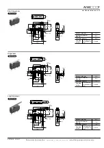
Roller lever
3.2
5.0 dia.
NO
NC
C
2.5 max.
6.4
5.2
1.25
0.5
(P.T.)
±
0.1
±
0.2
1.1
±
0.12
1.5
±
0.12
1.85
±
0.2
2.2
0.5
8.7
15.4
0.9
7.4
0.75
9.5
7.7
-0.05
+0.1
2.4
2.4
19.8
2.5
±
0.1
±
0.15
±
0.15
±
0.3
±
0.1
2.2
±
0.1
±
0.15
3.4
6.7
2.4
dia.
+0.1
-0.05
14.5
±
0.8
(O.P.)
17.9
(O.P.)
±
0.9
5.15
±
0.4
12.85
Pretravel, Max. mm
2.5
Movement differential,
Max. mm
0.5
Overtravel, Min mm
0.8
Operating
position
Distance from
mounting hole,
mm
14.5
±
0.8
CAD Data
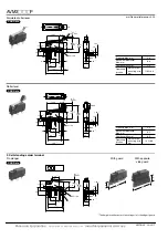
2. Self-standing solder terminal
Pin plunger
0.6 max.
8.7
15.4
R0.8
2.4
2.8
7.4
9.5
1.8
6.4
5.2
1.25
0.5
4.0
(P.T.)
7.7
-0.05
+0.1
2.4
2.4
19.8
2.5
NO
NC
C
7.6
±
0.3
±
0.1
±
0.15
±
0.15
±
0.3
±
0.2
2.2
±
0.1
±
0.15
3.4
R0.6
±
0.1
±
0.2
1.1
±
0.12
1.5
±
0.12
1.85
±
0.2
6.7
8.4
±
0.25
(O.P.)
11.8
(O.P.)
±
0.35
2.4
dia.
+0.1
-0.05
With guard
8*
24
With opposite
side guard
24
8*
* The height from the center of mounting hole to the edge of guard.
CAD Data
AECTB12E 201201-T
Panasonic Corporation
Automation Controls Business Unit
industrial.panasonic.com/ac/e

