background image

AVM3

P

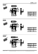
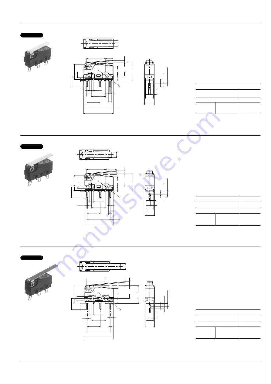
Short hinge lever

12.85

NO

NC

C

5.0

±

0.4

2.5 max.

6.4

5.2

1.25

0.5

4.0

(P.T.)

±

0.1

±

0.2

1.1

±

0.12

1.5

±

0.12

1.85

±

0.2

2.2

0.5

8.7

15.4

0.9

7.4

0.75

9.5

7.7

-0.05

+0.1

2.4

2.4

19.8

2.5

±

0.1

±

0.15

±

0.15

±

0.3

±

0.1

2.2

±

0.1

±

0.15

3.4

6.7 8.8

±

0.8

(O.P.)

12.2

(O.P.)

±

0.9

2.4

dia.

+0.1

-0.05

Pretravel, Max. mm

2.5

Movement differential, 
Max. mm

0.5

Overtravel, Min mm

0.8

Operating 
position

Distance from 
mounting hole, 
mm

8.8

±

0.8

mm General tolerance: 

±

0.25

CAD Data

Hinge lever

NO

NC

C

7.15

±

0.4

12.85

2.8 max.

6.4

5.2

1.25

0.5

4.0

(P.T.)

±

0.1

±

0.2

1.1

±

0.12

1.5

±

0.12

1.85

±

0.2

2.2

0.5

8.7

15.4

0.9

7.4

0.75

9.5

7.7

-0.05

+0.1

2.4

2.4

19.8

2.5

±

0.1

±

0.15

±

0.15

±

0.3

±

0.1

2.2

±

0.1

±

0.15

3.4

6.7 8.8

±

0.8

(O.P.)

12.2

(O.P.)

±

0.9

2.4

dia.

+0.1

-0.05

Pretravel, Max. mm

2.8

Movement differential, 
Max. mm

0.8

Overtravel, Min mm

1.2

Operating 
position

Distance from 
mounting hole, 
mm

8.8

±

0.8

CAD Data

Long hinge lever

NO

NC

C

13.1

±

0.4

12.85

3.5 max.

6.4

5.2

1.25

0.5

4.0

(P.T.)

±

0.1

±

0.2

1.1

±

0.12

1.5

±

0.12

1.85

±

0.2

2.2

0.5

8.7

15.4

0.9

7.4

0.75

9.5

7.7

-0.05

+0.1

2.4

2.4

19.8

2.5

±

0.1

±

0.15

±

0.15

±

0.3

±

0.1

2.2

±

0.1

±

0.15

3.4

6.7

8.8

±

1.2

(O.P.)

12.2

(O.P.)

±

1.3

2.4

dia.

+0.1

-0.05

Pretravel, Max. mm

3.5

Movement differential, 
Max. mm

1.0

Overtravel, Min mm

1.6

Operating 
position

Distance from 
mounting hole, 
mm

8.8

±

1.2

CAD Data

AECTB12E  201201-T

Panasonic Corporation   

Automation Controls Business Unit

   industrial.panasonic.com/ac/e

Содержание AVM3P (PS)

Страница 1: ...witch Actuators 0 1 2 3 4 5 Pin plunger Short hinge lever Hinge lever Long hinge lever Simulated roller lever Roller lever Terminals 1 2 3 4 Self standing solder terminal with guard Self standing solder terminal without guard Self standing solder terminal with opposite side guard Self standing PC terminal Operating force by pin plunger max 5 1 47 N Capacity P High capacity 10 1 A Agency standard 9...

Страница 2: ...erature 25 to 85 C Not freezing below 0 C Unit weight Approx 2g Contact material AgNi alloy Actuator Operating force Max Release force Min Pretravel Max mm Movement differential Max mm Overtravel Min mm Operating position mm Pin plunger 1 47 N 0 20 N 0 6 mm 0 1 mm 0 4 mm 8 4 0 25 mm Short hinge lever 0 59 N 0 039 N 2 5 mm 0 5 mm 0 8 mm 8 8 0 8 mm Hinge lever 0 54 N 0 034 N 2 8 mm 0 8 mm 1 2 mm 8 8...

Страница 3: ... 9 5 7 7 0 05 0 1 2 4 2 4 19 8 2 5 0 1 0 15 0 15 0 3 0 1 2 2 0 1 0 15 3 4 6 7 8 8 0 8 O P 12 2 O P 0 9 2 4 dia 0 1 0 05 Pretravel Max mm 2 8 Movement differential Max mm 0 8 Overtravel Min mm 1 2 Operating position Distance from mounting hole mm 8 8 0 8 CAD Data Long hinge lever NO NC C 13 1 0 4 12 85 3 5 max 6 4 5 2 1 25 0 5 4 0 P T 0 1 0 2 1 1 0 12 1 5 0 12 1 85 0 2 2 2 0 5 8 7 15 4 0 9 7 4 0 75...

Страница 4: ... 7 0 05 0 1 2 4 2 4 19 8 2 5 0 1 0 15 0 15 0 3 0 1 2 2 0 1 0 15 3 4 6 7 2 4 dia 0 1 0 05 14 5 0 8 O P 17 9 O P 0 9 5 15 0 4 12 85 Pretravel Max mm 2 5 Movement differential Max mm 0 5 Overtravel Min mm 0 8 Operating position Distance from mounting hole mm 14 5 0 8 CAD Data 2 Self standing solder terminal Pin plunger 0 6 max 8 7 15 4 R 0 8 2 4 2 8 7 4 9 5 1 8 6 4 5 2 1 25 0 5 4 0 P T 7 7 0 05 0 1 2...

Страница 5: ... the terminals during soldering Terminal portions must not be moved in min 1 minute after soldering Also no tensile strength of lead wires should be applied to terminals 3 Selection of the switch When specifying the switch allow 20 to the listed operating characteristics 4 Environment Avoid using the switches in the following conditions In corrosive gases such as silicon gas In a dusty environment...

Отзывы: