background image

10

11

Parts and their functions 

(continued)

6. 

Auto Setup button <SETUP>

Use this button to start auto setup.

The setup status is output to the picture monitor.

Choose [FUNCTION] 

 [ASU SETUP] in the ROP menu to select 

[OUT FULL] or [OUT EASY] mode.  (For details, refer to Operations 

and Settings on the supplied CD-ROM)

OUT FULL:

Standard setup based on an outdoor shooting chart

<Sequence of operation execution>

AWB→ABB→BSHD→ABB→AWB→FLARE→AWB

OUT EASY:

Easy setup based on an outdoor shooting chart

<Sequence of operation execution>

AWB→ABB→AWB→FLARE→AWB

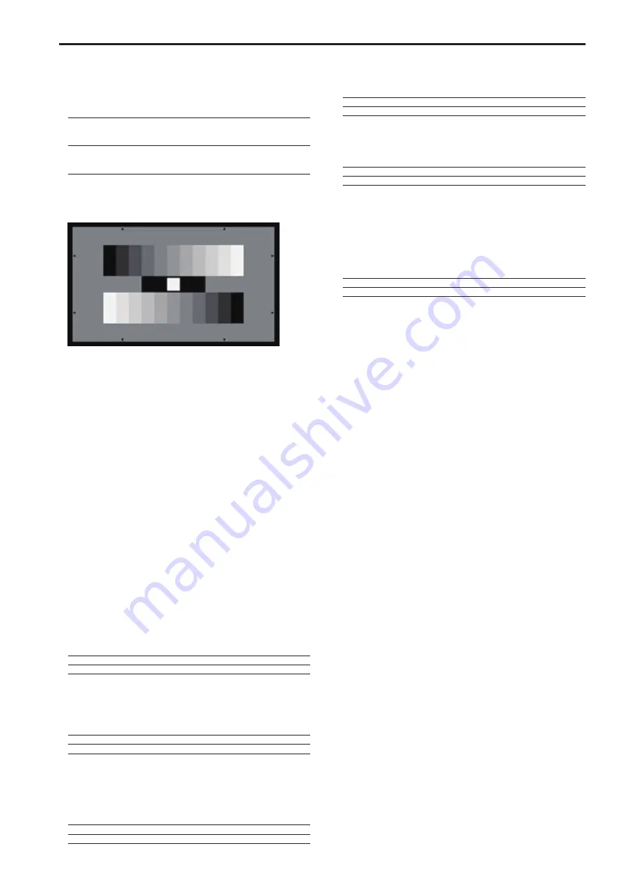
Align the position of the gray scale wedge with the angle of view in 

the vertical direction of the viewfinder. Be sure to correctly select the 

position from which you shoot the chart since some positions may not 

enable a satisfactory auto setup.

(Recommended gray scale)


z

Starting auto setup

1. Press <SETUP>.

<SETUP> flashes at about 2-second intervals while the auto 

setup start preparation mode is established, and a square 

marker appears in the center of the camera viewfinder. Align 

the white at the center of the gray scale with this square marker. 

(To cancel setup button, press and hold the switch.)

2. Press <SETUP> again.

<SETUP> lights as auto setup starts. (Pressing <SETUP> 

during the auto setup operation will abort auto setup.)

<SETUP> goes off when auto setup ends successfully.

If <SETUP> flashes at approximately 1-second intervals, auto 

setup has ended without being completed. During the auto 

setup operation, the picture monitor (PM) displays characters to 

indicate operation status.

<Note>

If auto setup is not completed, check the message on the picture 

monitor (PM) on the CCU.

7. 

5600 K button <5600K>

Use this function to change the amplification rate of the RB signals 

by an electrical circuit to achieve a white balance that corresponds 

to a 5600K color temperature. When the 5600K button <5600K> is 

set to On, the B video signal is attenuated by about −6 dB, the R 

video signal is boosted by about 3 dB while the G video signal is not 

attenuated.

Select this setting for shooting under a 5600K light source or when 

shooting outdoors.

On:

ON

Off:

OFF

8. 

Matrix button <MATRIX>

Use this function to correct saturation and color phase according to 

the gain setting of each color component in matrix memory. Each 

press of the button turns the function on or off.

On:

ON

Off:

OFF

9. 

Skin Detail button <SKINDTL>

Use this button to apply coring to the detail enhancement of the skin 

tone areas in the HDTV video output signals to soften or increase the 

enhancement of skin tone details. Each press of the button turns the 

function on or off.

On:

ON

Off:

OFF

10. 

Knee OFF button <KNEE OFF>

Use this button to cancel the knee function that attenuates those 

areas of the video signals where a particular level (knee point) has 

been exceeded so that they will not become saturated as easily.

On:

Knee function is canceled. (Knee OFF)

Off:

Knee function is on.

11. 

Detail OFF button <DTL OFF>

Use this button to cancel contour enhancement (hard/soft) (detail 

enhancer) of image output.

On:

Turns off contour enhancement (detail enhancer off)

Off:

Turns on contour enhancement (detail enhancer on)

12. 

 Shutter On/Off button <SHUTTER ON>

STEP/SYNC select button<STEP/SYNC>

Use thus button to turn the SHUTTER on or off. Press and hold the 

button to switch between STEP and SYNCRO. In SHUTTER ON 

mode, the SHUTTER display select button <SHUTTER> and the 

SHUTTER display <SHT> goes on, and the setting appears on the 

setting display for about 2 seconds.

On:

SHUTTER ON (STEP/SYNCRO setting is available)

Off:

SHUTTER OFF (STEP/SYNCRO setting is available)

Содержание AK-HRP200GJ

Страница 1: ...vided as a PDF file on the CD ROM supplied with the unit To read PDF files you will need Adobe Reader You can download it from Adobe Systems website SS1012KT0 PS Printed in Japan ENGLISH Before operating this product please read the instructions carefully and save this manual for future use DEUTSCH Für Erlauterungen in Deutsch konsultieren Sie bitte die mitgelieferte CD ROM Seite 4 FRANÇAIS Pour d...

Страница 2: ... This equipment has been tested and found to comply with the limits for a class A digital device pursuant to Part 15 of the FCC Rules These limits are designed to provide reasonable protection against harmful interference when the equipment is operated in a commercial environment This equipment generates uses and can radiate radio frequency energy and if not installed and used in accordance with t...

Страница 3: ...ces IMPORTANT SAFETY INSTRUCTIONS 1 Read these instructions 2 Keep these instructions 3 Heed all warnings 4 Follow all instructions 5 Do not use this apparatus near water 6 Clean only with dry cloth 7 Do not block any ventilation openings Install in accordance with the manufacturer s instructions 8 Do not install near any heat sources such as radiators heat registers stoves or other apparatus incl...

Страница 4: ...r sur le nom du document correspondant au manuel à consulter Adobe Reader est nécessaire pour lire les fichiers PDF Ce logiciel peut être téléchargé depuis la page d accueil d Adobe Systems ITALIANO Come aprire i file dei manuali di istruzioni per l uso Se inserendo il CD ROM si apre la schermata di installazione del software interrompere l installazione Aprendo INDEX pdf sul CD ROM viene visualiz...

Страница 5: ...y card will be used below as a generic term for both SD and SDHC memory cards SD or SDHC will be used in descriptions that refer to only one of the two card types A studio handy camera is referred to as a camera in this manual A camera control unit is referred to as a CCU in this manual A remote operation panel is referred to as an ROP in this manual Illustrations and screen displays in this manua...

Страница 6: ...sing and storing the unit Avoid locations exposed to high temperature and humidity Avoid exposure to condensation Avoid static electricity Software upgrades For upgrades visit Support Download on the Panasonic website http pro av panasonic net Follow the instructions included in the download file to perform the upgrade Disclaimer Panasonic Corporation will not accept any liability whatsoever for a...

Страница 7: ...sure to temperatures below 0 C 32 F or above 40 C 104 F could adversely affect Internal components Power off before connecting or disconnecting cables Connect and disconnect cables when the unit is turned off when the CCU is off the ROP cable is disconnected and an external DC power supply is not connected Avoid humidity and dust Avoid using the unit in an excessively humid or dusty location to pr...

Страница 8: ...amaged Do not install the unit in a location where the temperature drops to 0 C 32 F or lower or reaches 40 C 104 F or higher Do not install the unit in a location exposed to direct sunlight or near exhaust vents that expel hot air Do not install the unit in a location exposed to excessive humidity dust or vibrations to prevent malfunction Setting up the unit Installing and removing rack mount bra...

Страница 9: ...connecting the ROP cable Outside dimension drawing Unit mm inch GAIN AUTO BLACK SET UP WHITE BARS TEST VF POWER HEAD POWER DTL OFF SHUTTER ON STEP SYNC KNEE OFF SKINDTL MATRIX 5600K SCENE 4 STORE SCENE 3 SCENE 2 SCENE USER FILE SCENE 1 USER 3 USER 2 USER 1 SHIFT FLARE PED CAMERA No DTL DATA SET DISPLAY SELECT UP DOWN SET UP ND CC M GAIN M PED SHUTTER ND VR LOCK M GAIN IRIS M PED 10 19 CC SHT SYNC ...

Страница 10: ... press and hold the Color Bar Signal Output BARS TEST button to select the TEST signal To switch from TEST signal output press the Color Bar Signal Output button BARS TEST to select camera video output On yellow CCU color bar and camera color bar On On green TEST signal On Off Camera video 4 Auto White Balance button WHITE Use this button to automatically adjust the white balance On This indicates...

Страница 11: ... amplification rate of the RB signals by an electrical circuit to achieve a white balance that corresponds to a 5600K color temperature When the 5600K button 5600K is set to On the B video signal is attenuated by about 6 dB the R video signal is boosted by about 3 dB while the G video signal is not attenuated Select this setting for shooting under a 5600K light source or when shooting outdoors On ...

Страница 12: ...hile the scene file is being opened or after it has opened will persist when the power is turned off z z Opening a user file Hold down SHIFT while pressing the SCENE USER FILE select button SCENE1 USER1 to SCENE3 USER3 for the number of the scene file 1 to 3 you want to open The pressed button lights and the user file opens in about 1 second About a second later the button goes off Note Opening a ...

Страница 13: ...et to the paint control value stored in step 2 17 R gain control GAIN R Use this control to adjust the red R components of the white balance It is controlled by control lock VR LOCK 18 B gain control GAIN B Use this control to adjust the blue B components of the white balance It is controlled by the control lock VR LOCK 19 R flare pedestal control FLARE PED R Use this control to adjust the red R c...

Страница 14: ...splay and change set values for the ND or CC filters On white Displays the ND filter and CC filter settings Off Displays settings other than the ND filter and CC filter settings Note The CC filter cannot be used on the AK HC3800 studio handy camera z z Setting and displaying the ND filter and CC filter 1 Press ND CC when IRIS or other M GAIN M PED or SHUTTER DISPLAY SELECT status is displayed The ...

Страница 15: ... setting is always available regardless of display status 32 SHUTTER DISPLAY SELECT button SHUTTER EXECUTE button EXECUTE In setup mode Press this button to display and change SHUTTER settings Note When the Shutter On Off button SHUTTER ON is set to Off the SHUTTER DISPLAY SELECT button SHUTTER is available and the SHUTTER can be adjusted Adjustments can be made prior to operation z z Setting and ...

Страница 16: ... the button when it is not on will light it Pressing it when it is on will light turn it off Pressing it when it is on or off will light the Call lamp on the CCU and the indicator TALLY on the camera Pressing the call switch on the camera or CCU sounds the unit buzzer It stays on as long as the switch is depressed when the buzzer is set to On The tally also lights red when the button is off but go...

Страница 17: ...ard adjusts the auto iris level in CLOSE direction Moving it to the rear adjusts it in the OPEN direction On The auto iris mode is enabled Off Manual manual adjustment using the iris bar is possible For details on auto iris settings refer to ROP menu setting in Operations and Settings on the supplied CD ROM 49 Iris close button CLOSE Use this button to forcibly set the iris to CLOSE On Forcibly se...

Страница 18: ...ow Remarks 1 P VIEW1 ROP external control Dry contact 2 P VIEW2 ROP external control Dry contact 3 EXTRA1 External control ROP For future connections 4 EXTRA2 External control ROP For future connections 3 RS 422 connector RS 422 RJ 45 connector This connector is designed for future use Do not use this connector 4 IP connector LAN RJ 45 connector This connector is designed for future use Do not use...

Страница 19: ...on 9 Control lock 13 Control lock button 13 D DATA SET button 14 Detail OFF button 11 Digital extender indicator 17 Dip Switche 18 DTL control 13 E EXECUTE button 15 EXIT button 15 F Fader full button 17 I IP connector 18 Iris close button 17 IRIS display 14 Iris lever 17 Iris master pedestal lock button 16 K Knee OFF button 11 L Lens extender indicator 17 M Master pedestal control 17 Matrix butto...

Страница 20: ...uivalent new product Disposing of this product correctly will help to save valuable resources and prevent any potential negative effects on human health and the environment which could otherwise arise from inappropriate waste handling Please contact your local authority for further details of your nearest designated collection point Penalties may be applicable for incorrect disposal of this waste ...

Отзывы: