background image

8

Status Displays

Each status item consists of six characters.
The item designation appears on the first line and its status on the second line.
Three items can be indicated simultaneously on the unit’s display panel.
Using the scroll buttons, the displays can be scrolled to the left or right to display other items.

Example of display:

V

VI

ID

D_

_I

IN

N E

EN

NC

CF

FM

MT

T E

EN

NC

CF

FL

LD

D

H

HD

D_

_S

SD

DI

I 1

10

08

80

0i

i  5

59

9.

.9

94

4

Display

sequence

Status

display

item

Status displayed

2

ENCFMT

Displays the format of the video
signals to be encoded.

1080i: 

1080i format signals are
encoded.

720P: 

720P format signals are
encoded.

3

ENCFLD

Displays the field frequency of the
signals to be encoded.

59.94: 

The signals are encoded with a
field frequency of 59.94 Hz.

4

TC

Indicates whether the time code is in
the drop frame or non-drop frame
mode.

DF: 

Drop frame mode.

NDF: 

Non-drop frame mode.

5

TC_IN

Displays the status of the time code
input signal.

LTC: 

The LTC signal of the TIME
CODE IN connector is used as
the time code input.

SLTC: 

The LTC information added to
the HD SDI signal is used as
the time code input.

SVITC: 

The VITC information added
to the HD SDI signal is used
as the time code input.

<Note>

Each display flashes if the
corresponding time code signal is not
input.

6
7
8
9

A12_IN
A34_IN
A56_IN
A78_IN

Displays the status of the audio input
signals.

AES:

The AES audio signals of the
DIGITAL AUDIO IN connectors
are used as the audio input
signals.
The display flashes if the AES
audio signals are not input.

SDI:

The HD SDI embedded audio
signals are used as the audio
input signals.
The display flashes if the HD
SDI signal is not input or if the
audio signal is not embedded
even when it is input.

INT_SG: 

The signals of the internal signal
generator are used as the audio
input signals.

List of status display items

When the unit is used as an encoder

Display

sequence

Status

display

item

Status displayed

1

VID_IN

Displays the video input signal status.

HD_SDI: 

Indicates that HD SDI video
signals are input; flashes
when no signals have been
input.

INT_CB: 

Indicates that the video input
signal is the color bars
signal of the internal signal
generator.

INT_MB: 

Indicates that the video
input signal is the multi burst
signal of the internal signal
generator.

INTRMP: 

Indicates that the video
input signal is the ramp
signal of the internal signal
generator.

INTBLK: 

Indicates that the video input
signal is the black signal of
the internal signal generator.

Содержание AJ-HDP151P

Страница 1: ...DVCPRO HD Codec Unit AJ P Operating Instructions POWER INPUT ENTER ESCAPE SHIFT MENU SET DIAG ON OFF ...

Страница 2: ...ued compliance follow the attached installation instructions and do not make any unauthorized modifications This equipment has been tested and found to comply with the limits for a class A digital device pursuant to Part 15 of the FCC Rules These limits are designed to provide reasonable protection against harmful interference when the equipment is operated in a commercial environment This equipme...

Страница 3: ...Connectors 21 Specifications 22 The AJ HDP151P is a codec encoder decoder unit which is used in combination with an HD SD multi format DVCPRO server AJ HDR150 to record and play back DVCPRO HD high definition format signals Switching between the encoder and decoder is accomplished by means of setup menu operations HD signals can be recorded and played back in the AJ HDR150 by fitting the optional ...

Страница 4: ...that setting has been selected 7SHIFT button This is pressed together with the button or 2 button to change the mode encoder decoder etc during the setup menu setting process 8MENU button This is pressed when a setup menu is to be operated When it is pressed the setup menu number and item appear on the display panel When a video monitor has been connected to the HD SDI OUT3 connector or SD SDI OUT...

Страница 5: ...ors ENCODER REMOTE connector The encoder remote controller is connected here to enable the video output signal settings to be adjusted 1AC IN socket AC IN The power cable provided with the unit is connected here 2SIGNAL GND terminal This is the grounding terminal to reduce the noise level It is connected with the signal ground terminal on the component to which the unit is connected This is not a ...

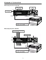
Страница 6: ... signal The SDTI I O circuit board AJ YAC7000P is required for the AJ HDR150 LTC if required When using the unit as a decoder PUSH IN OUT1 AUDIO CH1 2 CH3 4 CH5 6 CH7 8 SD REF IN IN IN OUT HD SDTI HD SDI OUT 3 SUPER OUT 2 OUT 1 OUT 2 SD SDI DIGITAL AUDIO OPTION OUT 3 SUPER AUDIO CH1 2 CH3 4 CH5 6 CH7 8 OUT HD REF ENCODER REMOTE TC IN SIGNAL GND TC OUT AC IN FUSE 125V 5A T IN HD REF OUT ON OFF 75 O...

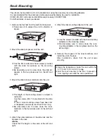
Страница 7: ...temperature inside the rack within the 41 F to 95 F 5 C to 35 C range OBolt the rack securely to the floor to prevent it from toppling over when the unit is pulled out OUse the screws provided with the rack mounting adapters as the mounting screws OBe absolutely sure to screw down the rack mounting adapters in the two places each on the left and right OThe length of the mounting screws is subject ...

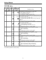
Страница 8: ... information added to the HD SDI signal is used as the time code input Note Each display flashes if the corresponding time code signal is not input 6 7 8 9 A12_IN A34_IN A56_IN A78_IN Displays the status of the audio input signals AES The AES audio signals of the DIGITAL AUDIO IN connectors are used as the audio input signals The display flashes if the AES audio signals are not input SDI The HD SD...

Страница 9: ...erator 59 94 Hz is used as the reference signal NTSC59 The HD REF input is used as the reference signal Its field frequency is 59 94 Hz INT59N SD REF is selected as the menu item 031 OUT REF setting but since this signal is not input the signal of the internal signal generator 59 94 Hz is used as the reference signal Display sequence Status display item Status displayed 6 UFC Displays the status o...

Страница 10: ...en SYSTEM ENC and SYSTEM DEC press the or 2 button in the menu setting mode while pressing the SHIFT button Switching between the encoder and decoder Whether the unit is to be used as an encoder or decoder is determined by the SYSTEM menu No 01 INPUT SEL setting OWhen HD SDI is selected as the INPUT SEL setting the unit functions as an encoder to convert HD SDI inputs into SDTI outputs OWhen SDTI ...

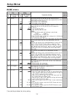
Страница 11: ...levels can be adjusted Note This setting takes effect when the unit is used as a decoder 12 SYS H HD 0550 1100 1650 500 0 500 For adjusting the system phase of the HD SDI output in 27 ns steps The phase is moved forward The phase is moved backward Note This setting takes effect when the unit is used as a decoder It remains unchanged even when the menu is initialized 13 V PHASE HD 0000 0500 1000 50...

Страница 12: ...imposed characters Note While this item is being set the superimposed display is output from the HD SDI OUT3 and SD SDI OUT3 connectors in accordance with the settings selected for DISPLAY SEL and CHARA TYPE even if OFF has been selected as the SUPER setting However it will be in accordance with the SUPER OFF or ON setting when the menu setting mode has been exited 009 CHARA TYPE 0000 0001 WHITE W...

Страница 13: ... the SD SDI output 507 EXT TC SEL 0000 0001 0002 LTC SLTC SVITC For selecting the time code to be embedded in the subcode area of the SDTI output signal 0 LTC from the TIME CODE input connector is selected 1 The LTC information embedded to the HD SDI input signal is selected 2 The VITC information embedded to the HD SDI input signal is selected 513 VITC OUT 0000 0001 SBC VAUX For selecting the VIT...

Страница 14: ...for 4 and below are recorded 1 The 8 bit signal which has been dynamically rounded is recorded 605 INTERPOLATE 0000 0001 OFF AUTO For selecting the interpolation operation During slow playback vertical interpolation is conducted automatically to reduce the vertical movement of the playback pictures However this operation can be forcibly turned off using this setting 0 Interpolation is forcibly tur...

Страница 15: ...hen REMOTE has been selected as the setup menu item No 05 ENCODER SEL setting 650 Y LVL HD 0000 1000 1413 0 0 100 0 141 3 For adjusting the Y level which is to be output to the HD SDI OUT connectors to 0 dB to 3 dB 651 Pb LVL HD 0000 1000 1413 0 0 100 0 141 3 For adjusting the PB level which is to be output to the HD SDI OUT connectors to 0 dB to 3 dB 652 Pr LVL HD 0000 1000 1413 0 0 100 0 141 3 F...

Страница 16: ... SD 0000 0001 OFF ON For selecting whether EDH is to be embedded in the SD SDI output 0 EDH is not embedded 1 EDH is embedded 676 SDI INDEX O 0000 0001 OFF ON For selecting whether the VIDEO INDEX signal is to be embedded in the SD SDI output 0 The VIDEO INDEX signal is not embedded 1 The VIDEO INDEX signal is embedded Item Setting No Superimposed display No Superimposed display Description of set...

Страница 17: ...he CH7 and CH8 input when USR SET has been selected as the setup menu item No 700 AUDIO IN SEL setting 0 The AES input signals are selected 1 The SDI input signals are selected 753 SD SDI CH1 SEL 0000 0001 CH1 CH5 For selecting the audio channel whose signals are to be output for CH1 of the SD SDI output 0 The CH1 signals are output 1 The CH5 signals are output 754 SD SDI CH2 SEL 0000 0001 CH2 CH6...

Страница 18: ... HD SD SDI OUT3 connector Characters displayed The background of the characters appearing as superimposed displays can be changed by setting setup menu item No 009 CHARA TYPE TCR 22 22 22 22 TV monitor T TC CR R 22 22 22 22 TV monitor TCR 22 22 22 22 TV monitor TCR 22 22 22 22 TV monitor TCR 22 22 22 22 TV monitor Abbreviation TCR time code value Operation mode The unit s operating mode can be dis...

Страница 19: ...not input TC NO INPUT Time code signal is not input REF NO INPUT Reference signal is not input DIAG Display If the front panel DIAG button is pressed while no setup menu operations are being performed the unit s hour meter OPERATION and warning message can be displayed on the display panel The hour meter and warning message will be superimposed onto the TV monitor display when a monitor has been c...

Страница 20: ...install the HD SD format converter board AJ UDC150P 4 Insert the board into the F4 slot engage the board clamps and screw them down Note Insert the board while ensuring that the wires are not pinched in the process 5 Unlock the stoppers place the board unit flat and screw it down Note Place the board unit flat while ensuring that the wires are not pinched in the process 6 Attach the top panel and ...

Страница 21: ...tocol transmit 14 REM RX Y Remote control protocol receive 15 REM RX Y Remote control protocol transmit AUDIO IN HD SERIAL IN DIGITAL BNCa1 AUDIO IN DIGITAL BNCa4 CH1 CH2 CH3 CH4 CH5 CH6 CH7 CH8 AES EBU format TIME CODE IN XLRa1 1 GND 2 HOT 3 COLD AUDIO OUT HD SERIAL OUT DIGITAL BNCa3 AUDIO OUT DIGITAL BNCa4 CH1 CH2 CH3 CH4 CH5 CH6 CH7 CH8 AES EBU format TIME CODE OUT XLRa1 1 GND 2 HOT 3 COLD VIDE...

Страница 22: ...HD SDI Y output gain to 3 dB HD SDI PB output gain to 3 dB HD SDI PR output gain to 3 dB HD SDI Y black level 10 HD SDI output system phase 0 5 H HD SDI output video phase 0 45 H SD SDI Y output gain to 3 dB SD SDI PB output gain to 3 dB SD SDI PR output gain to 3 dB SD SDI Y black level 10 SD SDI output system phase 0 5 H VIDEO Sampling frequency Y 74 25 MHz PB PR 37 125 MHz Quantizing 8 bits Vid...

Страница 23: ...rmat Serial digital outputs BNCa3 SMPTE 292M standard met OTHER CONNECTORS Time code input XLRa1 0 5 V to 8 V p p 10 kΩ Time code output XLRa1 low impedance 2 0 V p p 0 5 V p p with 600 Ω load Encoder remote D sub 15 pins ACCESSORIES Power cable with 3 conductors a1 2U rack mounting adapters a2 Screws for 2U rack mounting adapters a4 Slide rail spacers a2 Flat countersunk head screws for slide rai...

Страница 24: ...overnment Marketing Department 52 West Gude Drive Rockville MD 20850 301 738 3840 Broadcast PARTS INFORMATION ORDERING 9 00 a m 5 00 p m EST 800 334 4881 24 Hr Fax 800 334 4880 Emergency after hour parts orders 800 334 4881 TECHNICAL SUPPORT Emergency 24 Hour Service 800 222 0741 Panasonic Canada Inc 5770 Ambler Drive Mississauga Ontario L4W 2T3 905 624 5010 Panasonic de Mexico S A de C V Av angel...

Отзывы: