


ELE-39
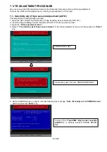
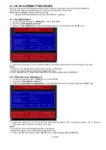
8. LCD ADJUSTMENT PROCEDURE
Be sure to save the VTR adjustment data into the Personal Computer, before performing adjustment.
Perform the all PC-EVR adjustments, by referring to procedures on PC screen.
Note:
Set to CAMERA mode in camera recorder.
Set the VTR TEST (SW103) switch on VFK1308P to L position.
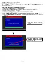
8-1. PLL Adjustment
1. Connect the oscilloscope to
“MON_PLL”
on the VFK1308P.
2. Open the
“LCD adjustment menu”
.
3. Select
“1. PLL adjustment”
in the LCD adjustment menu, and then press the
“Enter”
key.
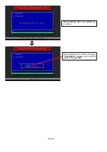
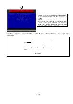
4. Adjust the arrow keys on PC so that the width (T) becomes 2.2±0.1µsec as shown in figure on screen.
Note:
1) Width (T) can be adjusted by pressing arrow keys on keyboard.
2) Waveform (figure) can be displayed by pressing F2 key.
5. When adjustment is finished, press ENTER key to white adjusted data to EEPROM.
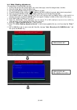
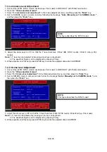
8-2. Pedestal Level Adjustment
1. Connect the oscilloscope to
“MON_G”
on the VFK1308P.
2. Open the
“LCD adjustment menu”
.
3. Select
“2. Pedestal Level adjustment”
in the LCD adjustment menu, and then press the
“Enter”
key.
4. Adjust the arrow keys on PC so that the differential amplitude both 0 step-level (portion
“a”
in figure) to
becomes 8.0±0.1V as shown in figure on screen.
Note:
1) Level (a) can be by pressing arrow keys on keyboard.
2) Waveform (figure) can be displayed by pressing F2 key.
5. When adjustment is finished, press ENTER key to white adjusted data to EEPROM.
Содержание AG-DVC30P
Страница 2: ...folder Go to Appendix List 2 ...
Страница 3: ...3 ...
Страница 4: ...4 ...
Страница 9: ...9 ...
Страница 31: ... 3 ...
Страница 32: ... 4 AG DVC30E ...
Страница 33: ... 5 ...
Страница 34: ... 6 AG MYA30G ...
Страница 36: ... 8 AG DVC30P ...
Страница 37: ... 9 AG DVC30E ...
Страница 38: ... 10 ...
Страница 39: ... 11 AG MYA30G ...
Страница 40: ...FCD0403NMHK141E480 ...
Страница 93: ...ELE 9 3 3 Introduction of the Sub Menu 1 Camera Check Menu 2 Video Check Menu 3 Camera Adjustment Menu ...
Страница 94: ...ELE 10 4 Video Adjustment Menu 5 LCD Adjustment Menu 6 EVF Adjustment Menu ...
Страница 155: ...LCD PARTS ASSEMBLY MPL 5 1 2 4 3 101 104 101 102 102 6 7 8 9 5 E23 9 3 9 2 9 4 9 1 103 ...
Страница 230: ...ELE 9 3 3 Introduction of the Sub Menu 1 Camera Check Menu 2 Video Check Menu 3 Camera Adjustment Menu ...
Страница 231: ...ELE 10 4 Video Adjustment Menu 5 LCD Adjustment Menu 6 EVF Adjustment Menu ...
Страница 276: ...SCHEMATIC DIAGRAMS NOTE BE SURE TO MAKE YOUR ORDERS OF REPLACEMENT PARTS ACCORDING TO PARTS LIST SECTION8 ...
Страница 335: ...LCD PARTS ASSEMBLY MPL 5 1 2 4 3 101 104 101 102 102 6 7 8 9 5 E23 9 3 9 2 9 4 9 1 103 ...


