INSTALLATION (CONTINUED)
ELECTRICAL CONNECTIONS
WARNING:
All electrical connections must be performed by a
qualified electrician. Make sure unit is off and disconnected from
power source while motor is mounted, connected, reconnected or
anytime wiring is inspected.
•
The motor is wired for 115 volts and in a clockwise rotation as
viewed from shaft end of motor.
•
The motor cord must be secured to protect the wiring connec-
tions from possible strain.
•
The power supply to motor is controlled by a locking rocker
switch. Power lines are connected to the quick connect termi-
nals of the switch.
•
The green ground line must remain securely fastened to the
motor ground terminal and drill press head to provide proper
grounding.
OPERATION
WARNING:
Read and understand operating instructions and
parts manual before operating this machine.
CAUTION:
The operation of any power tool can result in foreign
objects being thrown into the eyes, which can result in severe eye
damage. Always wear safety glasses complying with United States
ANSI Z87.1 (shown on package) before commencing power tool
operation.
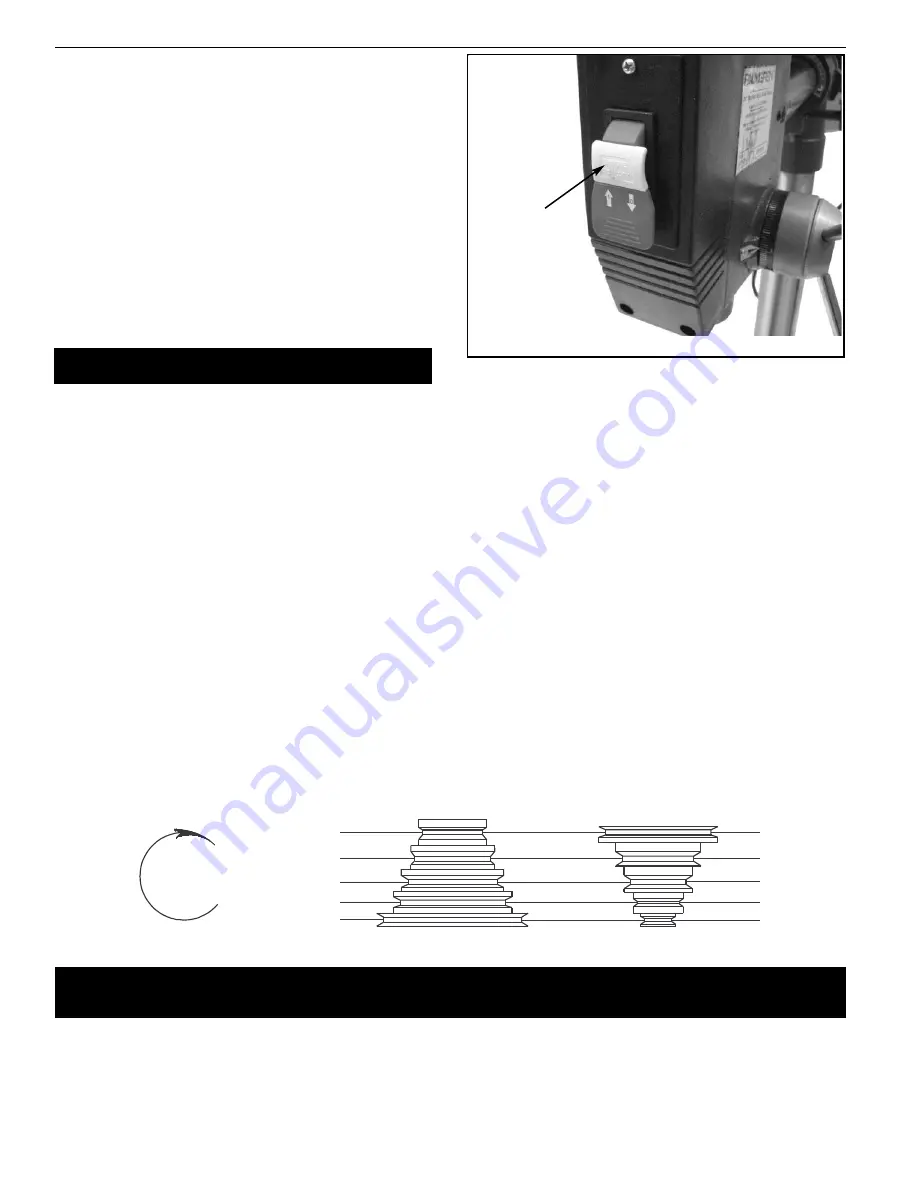
ON/OFF SWITCH
Refer to Figure 16.
The ON/OFF switch is located on the front of the drill press head.
To turn the drill press On, move the switch up to the ON
position. To turn the drill press Off, move the switch down to the
OFF position.
The drill press can be locked from unauthorized use by locking the
switch. To lock the switch:
•
Turn the switch to OFF position and disconnect drill press from
power source.
•
Pull the key out. The switch cannot be turned on with the key
removed.
NOTE: Should the key be removed from the switch at the ON posi-
tion, the switch can be turned off but cannot be turned on again.
•
To replace key, slide key into the slot on switch until it snaps.
SPEED ADJUSTMENTS
Refer to Figures 12 and 17.
WARNING:
Be sure drill press is turned off and is disconnected
from power source before adjusting speeds.
•
To change spindle speed, loosen motor lock knob (see Figure
14), and push the motor toward front of drill press. This will
loosen the belt and permit relocating the belt to the desired
pulley groove for the required spindle speed (See Figure 17.
•
After belt has been repositioned, push motor toward rear of
drill press and tighten motor lock knob.
•
Check belt for proper tension and make any final adjustment. A
belt is properly tensioned when light pressure applied to mid-
point of the belt produces about
3
/
8
” deflection.
HEAD ADJUSTMENTS
Refer to Figures 18 and 19, page 9.
WARNING:
Be sure drill is turned off and is disconnected from
power source before adjusting head.
•
Head can be tilted 45° right and 90° left.
•
To tilt head loosen head angle lock handle. Then pull out guide
pin and turn guide pin 90°.
•
Tilt head to desired angle, aligning reference mark on ram
with corresponding angle on the scale. Secure in
position by tightening head angle lock handle.
8
Palmgren Operating Manual & Parts List
80341A & 80342A
Figure 16 - Locking Key
Spindle
Rotation
5-5
4-4
3-3
2-2
1-1
3520
2630
1860
1120
575
in/mm
5/16 7.9
3/8
9.5
5/8 15.9
7/8 22.2
1
1
/
4
31.8
in/mm
3/16 4.8
1/4
6.4
3/8
9.5
1/2 12.7
3/4 19.0
in/mm
11/64
4.4
7/32
5.6
11/32
8.7
15/32 11.9
11/16 17.5
in/mm
5/32
4.0
3/16
4.8
5/16
7.9
7/16
11.1
5/8
15.9
in/mm
7/64
2.8
1/8
3.2
1/4
6.4
11/32
8.7
1/2
12.7
in/mm
3/32
2.4
3/32
2.4
5/32
4.0
1/4
6.4
3/8
9.5
in/mm
1/16
1.6
1/16
1.6
1/8
3.2
3/16
4.8
5/16
7.9
in/mm
1/32 0.8
3/64 1.2
1/16 1.6
1/8
3.2
1/4
6.4
Belt
Location
RPM
Wood
Zinc
Diecast
Alum. &
Brass
Plastic
Cast Iron
& Bronze
Steel
Mild &
Malleable
Steel Cast &
Med.
Carbon
Steel
Stainless &
Tool
Figure 17 – Spindle Speed Adjustment
Recommended Drill Size per Material for 5 Speeds
5
4
3
2
1
5
4
3
2
1
Spindle
Motor
Locking Key


