


2
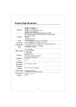
128K bytes buffer memory
Supports automatic loop detection and isolation
Support
s
9K bytes Jumbo Frames
Supports extensive LED indicators for network diagnostics
Internal power adapter
FCC, CE
and LVD
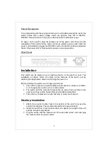
The Front Panel
The front panel consists of LED indicators. For detailed LED definition, please
refer to the next paragraph.
LEDs Definition
System LED
LED
Status
Operation
PWR
Steady Blue
The switch is powered on
Off
The switch is powered off
LOOP
Blinking Red
Off
There is a loop
There is no loop
Port LEDs
LED
Status
Operation
LINK/ACT
Steady Blue Valid port connection.
Blinking Blue
Valid port connection and there is data
transmitting/ receiving
Off
Port disconnected
or the port is connected at 10
Mbps or 100 Mbps
PoE
Steady Blue
A PoE compliant devices is connected to the
port
Off
No PoE complaint device is connected to the
port


