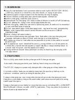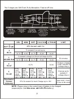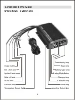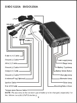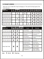
MOUNTING
WIRING
2
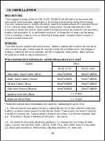
Recommended minimum cable dimensions in mm
*Note the above recommendation is valid for cable length up to 12m.
10. INSTALLATION
Cable
Alternator Input Cable (Red)
Solar Input Cable (Green)
Output Cable (Grey)
Common Ground (Black)
Ignition Override (Blue)
External LED (Pink)
Size
2
8mm /AMG8
2
8mm /AMG8
2
8mm /AMG8
2
8mm /AMG8
2
1-1.5 mm
2
1-1.5 mm
12
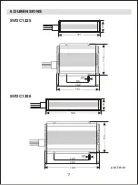
The rugged design of the SVDC1225 / SVDC1250 affords it to be mounted
wherever best suits the application. By using advanced potting technology
the unit is resistant to shock,vibration, dust and water allows for under-bonnet
or in-vehicle installation. Clever'side extrusions' incorporated within the
enclosure allow the unit to be mounted to flat surfaces as close to the auxiliary
battery as possible. It is advisable however to keep the charger as far away
from exhausts, turbo's or any other high temperate components to ensure
improved performance.
To make sound electrical connections, battery cables will need to be made to
the correct length. Cable lugs should be crimped or soldered to the stripped
battery cable and then protected with the supplied heat shrink. Butt splices
should be used for cable extension.
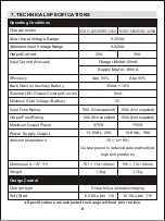
SVDC1225
SVDC1250
2
10mm /AMG8
2
10mm /AMG8
2
10mm /AMG8
2
10mm /AMG8
(1). Disconnect the negative battery cable (Earth) from the vehicle's starting
battery or disconnect power to the trailer. Note: To prevent the loss of vehicle
electronic memories, radio presets & security codes, it is recommended that
an
Electrical System Memory Protector
be used.
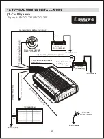
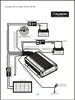
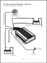
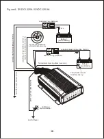
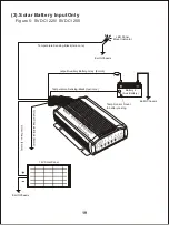
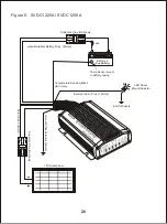
(2). Connect the Auxiliary Battery positive (+) terminal to the Output Cable
(grey colour) from SVDC1225 / SVDC1250. Fit a 50A /100A fuse to the cable
as close as possible to the Auxiliary Battery positive (+) terminal.


