


©2001 PACE Inc., Laurel, Maryland
Page 9 of 20
All Rights Reserved
System Power Up
1.
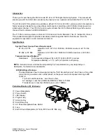
Insert the female end of the power cord into the AC Power Receptacle on the rear panel of
the power source.
2. Plug the prong end (male end) of the power cord into an appropriate 3 wire grounded AC
supply receptacle.
CAUTION:
To insure operator and ESD/EOS safety, the AC power supply receptacle must be
checked for proper grounding before initial operation.
NOTE:
Ensure that the system is placed in a well-ventilated area. Smoke will be generated
during the burn in cycle and while soldering. Fume extraction equipment is recommended
Burn In Procedure
Use the following instructions to perform the Heater Burn In procedure.
1.
Place the Power Switch in the “OFF” (0) position.
2.
Ensure that the handpiece is connected to the power source. If a plastic cap is present on
the heater assembly, remove it and discard. The cap is used for shipping purposes only.
3.
Press and hold the Program (
) and Scroll Up (
) keys together.
4.
Place Power Switch in “ON” (
I
) position.
5.
The display will read “brn” when the Program (
) and Scroll Up (
) keys
are released.
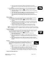
6. Press the (
) Key to initiate the Burn In Mode. The handpiece heater will
begin to heat. The temperature of the heater will stabilize at 315°C (600 °F)
for 10 minutes.
7.
At the conclusion of the 10-minute period, the heater temperature will
increase to 427°C (800°F) for 15 minutes.
8.
At the conclusion of the 15-minute time period, the heater is turned off and
the Display will read “End”. Press and release the Scroll Up Key (
) to exit
Heater Burn In and return the to normal operation.
CAUTION:
The heater will be hot at the conclusion of the Burn In procedure.
The microprocessor circuitry within the unit monitors the system and if any abnormalities are
encountered, the Burn In cycle will be interrupted and an error message displayed. Should
this occur, turn the system off and perform the procedure again. If the cycle is interrupted a
second time, refer to the Corrective Maintenance section of this manual.
This procedure should be performed whenever a new handpiece or heater is connected to
the system.
PS-70/PS-90 Tip Installation
For maximum productivity and proper fit, install tips into your soldering iron when
the heater is hot.
CAUTION:
To avoid burns or potential injury, always hold the
handpiece with the heater pointed at an angle up to prevent injury.
Installing PERMAGROUND Tips
1. PERMAGROUND Tips should be inserted into the heater with the tail
of the tip pointing towards the heater.
2. PERMAGROUND Tips can be used once the tip has been fully
inserted into the heater. The setscrew is not required to hold the
PERMA-
GROUND
Tip
Tip Tail
Heater


