


©2001 PACE Inc., Laurel, Maryland
Page 11 of 20
All Rights Reserved
Tip Temperature Compensation:
Differences between the temperature settings and true tip
temperatures are negligible when using Thru-Hole, single point soldering tips. With any heating
system however, True Tip Temperatures can differ greatly from temperature settings when using
larger SMT soldering tips. This difference is called Tip Temperature Offset. The ST 45 or ST 55
Auto Tip Temperature Compensation feature lets you set and display true tip temperatures
regardless of size and type of tip or handpiece. PACE recommends the use of the Tip &
Temperature Selection System booklet (PACE P/N 5050-0251) as a guide to accurately set and
maintain a true tip temperature for any size and type of SMT tip. The booklet contains a listing of
PACE tip information including the Tip Offset Constant (for each tip), which must be stored in
system memory to ensure tip temperature accuracy. Refer to the “Set-Up Mode” section of this
manual for instructions on using this feature.
The ST 45 or ST 55 system is very easy to adjust and operate. The following instructions detail
system features and operation of the system. Also included is a "Quick Start" procedure. Information
regarding changing of system options (e.g., Temperature Setback time, Auto Off) is contained in the
"Customizing Your System" portion of this manual.
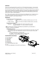
Quick Start Procedure
As received from the factory, the system can be quickly set up for use in standard soldering
operations. Simply perform the following Quick Start Procedure to begin using the system. The
systems can be stacked on each other for convenience and to preserve bench top space.
1.
Ensure that the Set-Up procedure has been performed; including the Heater Burn In
procedure. Check for the following:
a) Handpiece connection to the power source.
b) Proper tip installed in handpiece.
c)
Power cord connection between an appropriate AC supply receptacle and the
power source.
2.
Turn the Power Switch “On” (“I”).
3.
Press the Scroll Up (
) Key to enter the Temperature Adjust Mode.
4.
Press the Scroll Up (
) Key to increase the desired Tip Temperature.
Press the Scroll Down (
) Key to decrease the desired Tip Temperature.
5.
Press the Program Key (
). The system will now return to normal
operation.
6. Observe the Digital Readout as the temperature reaches and stabilizes at the Set Tip
Temperature
NOTE:
Read the “Operation” and "Customizing Your System" sections of this manual to utilize
the full capabilities of the system. This is especially important when using large soldering tips or
other SensaTemp handpieces.
IMPORTANT:
PACE recommends that you not read the “Customizing Your System” section
until after you feel comfortable with system operation. Please read the following “Operation"
section thoroughly before changing the system settings.
Operation
1.
Ensure that the Set-Up procedure has been performed; including the Heater Burn In
procedure. Check for the following:
a) Handpiece connection to the power source.
b) Proper tip installed in handpiece.
c)
Power cord connection between an appropriate AC supply and the power source.
2.
Turn the Power Switch On ("I").


