MTS Systems Operation Manual
©2004 PACE Inc., Annapolis Junction, Maryland
Page 6 of 11
All Rights Reserved
Handpieces
MTS systems can be used with any combination of TD-100 ThermoDrive Soldering Irons, MT-100
MiniTweezers, PS-70, PS-90, SX-70, SX-80, TT-65, TJ-70, TJ-80 and TP-65. All handpieces are
purchased separately. The MTS system’s handpiece ports are either black or red. Red ports can
connect to the TD-100 and MT-100 ONLY. The Black ports can be connected to the PS-70, PS-90,
SX-70, SX-80, TT-65, TJ-70, TJ-80 or TP-65. FIXED HEATER HANDPIECES CANNOT BE
CONNECTED TO THE RED PORTS AND HEATER CARTRIDGE HANDPIECES CANNOT BE
CONNECTED TO THE BLACK PORTS BECAUSDE THE CONNECTORS ARE NOT COMPATIBLE.
Handpiece Tip & Tool Stands
The Tip & Tool Stand is usually placed on the workbench next to the power source.
Adjusting the Angle of the Cubby
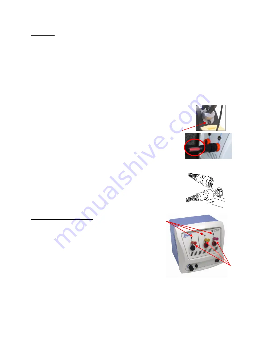
Some Handpiece Tip & Tool stands have adjustable cubbies. For example, the
angle of the TD-100 Cubby may be adjusted by loosening the angle thumb screw
slightly, adjusting the cubby to the desired angle, and tightening the thumb screw.
Handpiece Connection
When connecting a handpiece, always match the color on the connector
and handpiece port on the system. For example, HC handpieces have the
red connector and will only connect to red ports. Likewise, Fixed Heater
handpieces have black connectors and can only be connected to black
ports.
To connect the handpiece to the power supply, refer to the figure to the
right. Connect the handpiece connector plug into the Power Receptacle in
the following manner.
1. Align guide on the connector with slot on power receptacle.
2. Insert connector into power receptacle.
3. Turn the connector housing clockwise to lock in place.
Operation of the MTS Systems
MTS systems require the use of Power Modules. The Power
Module selects the desired heat/performance level for operation.
MTS systems come standard with two or three #7 Power
Modules. Additional Power Modules are available in performance
levels of 5, 5.5, 6, 6.5, 7.5, 8, and 8.5. Please refer to the
Accessory Section for Power Module part numbers. A heat level
of 5 corresponds to a nominal temperature of 500
F; a heat level
of 6.5 corresponds to a nominal temperature of 650
F, etc.
Actual temperatures may vary slightly due to tip geometry.
Verify the following:
a) Power cord connection between an appropriate AC supply receptacle and the power
source.
b) Handpiece connection to the power source.
c) Desired Power Module is installed.
Power
Module
Ports
LED
Indicators
Thumb Screw


