background image

MTS Systems Operation Manual  

©2004 PACE Inc., Annapolis Junction, Maryland 

Page 5 of 11 

All Rights Reserved 


Safety 


Safety Guidelines   


The  following  are  safety  precautions  that  personnel  must  understand  and  follow  when  using  or 
servicing this product. 


1.

  POTENTIAL  SHOCK  HAZARD  - 

Repair  procedures  on  PACE  products  should  be 

performed  by  Qualified  Service  Personnel  only.    Line  voltage  parts  may  be  exposed 
when the equipment is disassembled.  Service personnel must avoid contact with these 
parts when troubleshooting the product. 


2.  To  prevent  personnel  injury,  adhere  to safety  guidelines  in  accordance  with  OSHA  and 

other applicable safety standards.  

3.  SensaTemp handpiece heaters, installed tips, and heater cartridge tips are hot when the 

handpiece is powered on and for a period of time after power off.  

DO NOT

 touch either 

the heater or the tip.  Severe burns may result. 


4.  PACE  Tip  &  Tool  Stands  and  handpiece  cubbies  are  designed  specifically  for  use  with 

the  associated  handpiece  and  houses  it  in  a  manner  that  protects  the  user  from 
accidental  burns.    Always  store  the  handpiece  in  its  holder.    Be  sure  to  place  the 
handpiece in its holder after use and allow for cooling before storing.  


5.  Always use PACE systems in a well ventilated area.  A fume extraction system such as 

those  available  from  PACE  are  highly  recommended  to  help  protect  personnel  from 
solder flux fumes. 

6.  Exercise proper precautions when using chemicals (e.g., solder paste).  Refer to the Material 

Safety Data Sheet (MSDS) supplied with each chemical and adhere to all safety precautions 
recommended by the manufacturer. 

 
System Set-Up 

 
To set up an MTS system, use the following steps and associated images. 

 
1.  Store the shipping container in a convenient location.  Reuse of the  

container will prevent damage if you store or ship your system(s). 

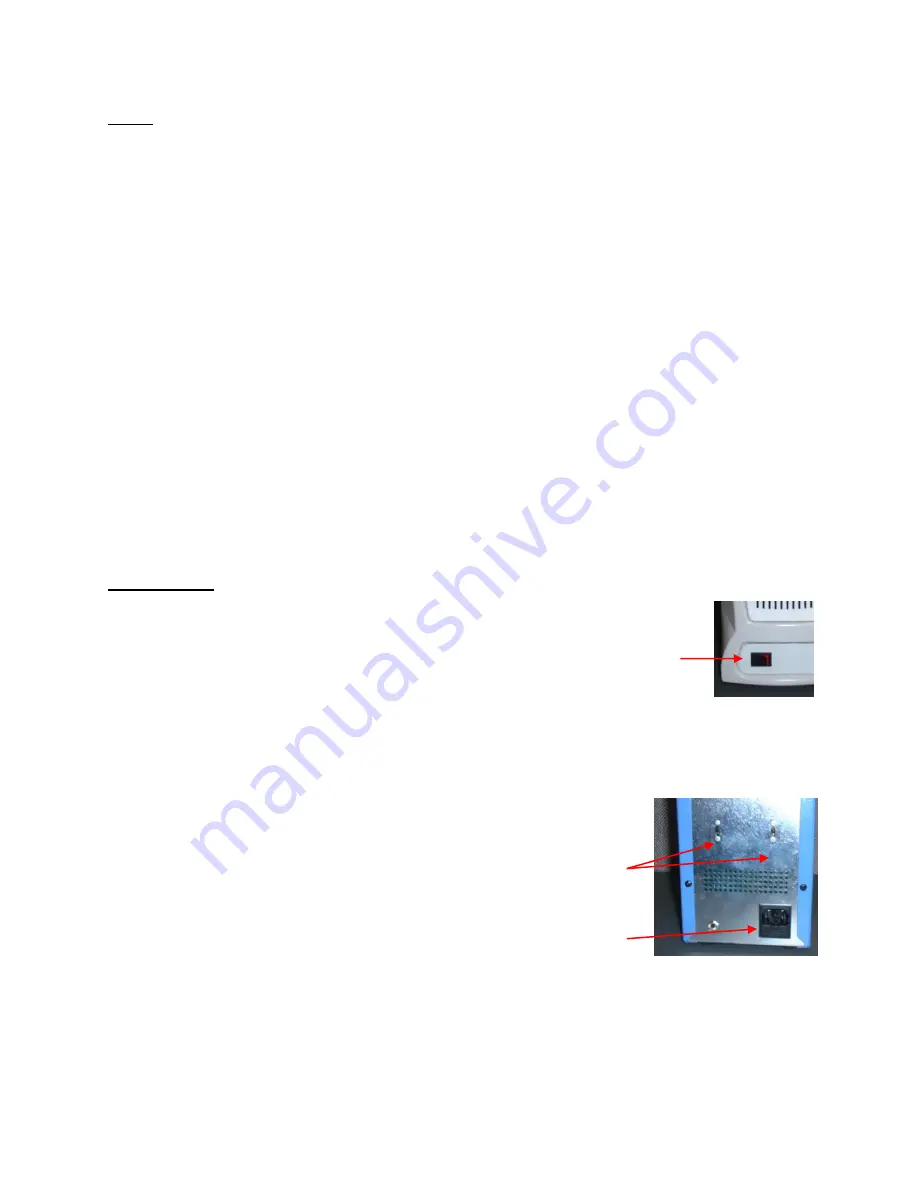
2. 

Place the Power Switch in the “OFF” or “0” position.   


Mounting Options 


1.  MTS systems can be placed directly on a work surface  
2.  MTS systems can be placed inside the optional Tool Chest.   

 
System Power Up 


1.  Insert the female end of the power cord into 

the  AC Power Receptacle  on the rear panel 
of the power source. 

2.  Plug the prong end (male end) of the power 

cord into an appropriate 3 wire grounded AC 
supply receptacle.   


CAUTION:   

To insure operator and ESD/EOS safety, the AC power 

supply receptacle must be checked for proper grounding before initial operation. 


NOTE: 

Ensure  that  the  system  is  placed  in  a  well-ventilated  area.    Fume  extraction     

equipment  is  recommended  when  melting  solder  or  heating  flux  or  flux  containing 
solders.   


Power 
Switch  

Setback/Auto-Off 
Switches 


AC Power 
Receptacle/Fuse 
Holder


Содержание MTS 200

Страница 1: ...VAC 8007 0414 MTS 200 SC System 230 VAC 8007 0415 MTS 200 SA System 115 VAC 8007 0412 MTS 200 SA System 230 VAC 8007 0413 MTS 300 System 115 VAC 8007 0418 B MTS 300 System 230 VAC 8007 0419 B MTS 350...

Страница 2: ...n 4 Safety 5 System Set Up 5 Mounting Options 5 System Power Up 5 Handpieces 6 Handpiece Tip Tool Stands 6 Adjusting the Angle of the Cubby 6 Handpiece Connection 6 Operation of MTS Systems 6 Vacuum P...

Страница 3: ...e FH channel the MTS 350 features 1 HC channel and 2 FH channels The system also comes standard with Auto Setback and Auto Off functions to preserve tip life Applicable Regulations MTS systems are ava...

Страница 4: ...1 3 Amp 115 VAC 60 Hz Max OR 7 Amp 230 VAC 50 Hz Max Fuse 2 Amp SloBlo 115 V System 1 Amp TimeBlo 230 V System MTS 350 1 3 Amp 115 VAC 60 Hz Max OR 7 Amp 230 VAC 50 Hz Max Fuse 2 Amp SloBlo 115 V Syst...

Страница 5: ...CE systems in a well ventilated area A fume extraction system such as those available from PACE are highly recommended to help protect personnel from solder flux fumes 6 Exercise proper precautions wh...

Страница 6: ...ector and handpiece port on the system For example HC handpieces have the red connector and will only connect to red ports Likewise Fixed Heater handpieces have black connectors and can only be connec...

Страница 7: ...Features These are pre programmed for 30 minute Auto Setback and 30 minute Auto Off which can be turned off by the switch on the back of the unit If the handpiece channel has not been used for 30 min...

Страница 8: ...iFilter FLOW OUT side into the power source Vacuum Port 3 When using air pressure and or utilizing multiple air handpieces PACE recommends the use of the following set up procedure which utilizes addi...

Страница 9: ...one of the same rated value Handpiece will not heat Defective Heater Change Tip Cartridge Power Source Malfunction Contact PACE Power Source Corrective Maintenance Packing Contents Description MTS 200...

Страница 10: ...WARRANTY OF MERCHANTABILITY OR FITNESS FOR A PARTICULAR PURPOSE Seller will at its option repair or replace any defective products at its facility or other location approved by it at no charge to user...

Страница 11: ...BRITE AUTO OFF and TEKLINK The following are registered trademarks and or service marks of PACE Incorporated Annapolis Junction Maryland U S A ARM EVAC FLO D SODR MINIWAVE PACE SENSATEMP SNAP VAC SOD...

Отзывы:

Похожие инструкции для MTS 200