Attaching Tip & Tool Stand to MBT 350
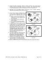
Attach the stand to the power source, using the following procedure. Refer to illustration.
1. Insert the 2 enclosed hex head Mounting Screws into the slot on the side of the Power Source. Some
kits may contain 4 mounting screws; 2 with small heads and 2 with large heads. Use the 2 screws that fit
properly in the slot. Also, some Power Source cases have more than 1 slot; use the lower slot.
Figure 4
2. Position the Mounting Screws to the rear of the power source and
spaced approximately 2 inches apart. Refer to illustration.
3. Place the Tip & Tool Stand beside the power source. Insert ends
of the 2 Mounting Screws into the 2 adjacent Tip & Tool
Stand mounting holes.
4. Install a Thumb Nut onto the end of each Mounting Screw. Tighten
Thumb Nuts to secure the Tip & Tool Stand in position.
You may wish to set the Power Source on its side and remove the
drip tray to ease installation of the Thumb Nut.
5. Additional Tip & Tool Stands or “cubby’s” may be secured to each
other by aligning mounting holes on stand sides. Use hex head
screws and thumb nuts to mount cubbys together.
Optional Instant-Setback Cubby
The optional Instant SetBack Cubby is available for use with the MBT 350 and will only function with the
TD-100 handpiece. When connected, it automatically puts the system into Setback mode when the TD-
100 is placed in the cubby. The Instant Setback Cubby will only function with the TD-100 Handpiece. The
MBT 350 is capable of using two Instant Setback Cubbys at the same time. The instant SetBack
receptacles are located on the back panel. See figure 3. The instant setback cubby's function is to protect
tips, not power off the system. Instant setback is a feature that lowers the temperature to 350°F after 45
seconds of inactivity. At 350°F the solder has solidified so any iron erosion on the tips ceases, protecting
the tip.
Tip Removal
Never remove a heated tip using bare hands. Use the Hot Grip Rubber Pad or Tip Tool.
Never use a wrench or pliers when removing a handpiece tips.
WARNING
©2005 PACE Inc., Annapolis Junction, Maryland All Rights Reserved Page 11 of 19


