


18
Calibration
The ST 20A system can be checked for calibration according to PACE requirements.
Also, a temperature setting normally used by the operator can be adjusted to the
precise temperature indicated on the Dial/Display. No internal adjustments can be
made to the power supply. To verify calibration of the power supply, perform the
following procedure.
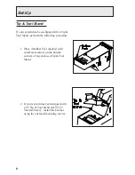
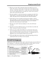
1. Install a tip with an attached thermocouple wire into the handpiece
connected to the system. Tips with K type thermocouples are available
from PACE; use part number 7021-0004-P1 when ordering.
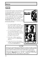
2. Connect the thermocouple assembly to a PACE Process Monitor (part
number 8001-0077 or 8001-0078) or appropriate temperature meter.
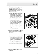
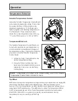
3. When set fully counterclockwise,the pointer
of the Variable Temperature Control knob
will align to the Calibration Mark as shown.
With the system turned on, adjust the
Variable Temperature Control to obtain a
stable tip temperature of 300°C (for PACE
factory specifications) or the temperature
setting normally used by the operator.
If the temperature displayed on the Process Monitor (or temperature meter)
is within ±5°C (10°F), perform steps 4 thru 6 to obtain a precise reading. If
the temperature is off by more than ±5°C, the handpiece may require
maintenance. Recheck the temperature using a second handpiece.
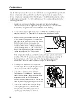
4. Carefully lock the Variable Temperature
Control in position by tightening the 2 inner
set screws (on Temp. Locking Ring).
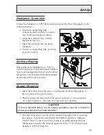
5. Loosen the set screw on the Variable
Temperature Control knob. Position the
knob with the pointer aligned to match the
temperature indicated on the Process
Monitor (or temperature meter). Secure the
knob in position by tightening the set screw.
6. Loosen the 2 inner set screws (on Temp.
Locking Ring) to unlock the Variable
Temperature control if adjustment of
operating tip temperature is desired.
Содержание 20A
Страница 1: ...Operation Maintenance Manual ST 20A Systems ...
Страница 26: ...24 ...