background image

Reverse Camera Input and Navigation Unlock 

Interface for Chrysler / Dodge / Jeep Vehicles

BCI-CH21

Pacific Accessory Corporation

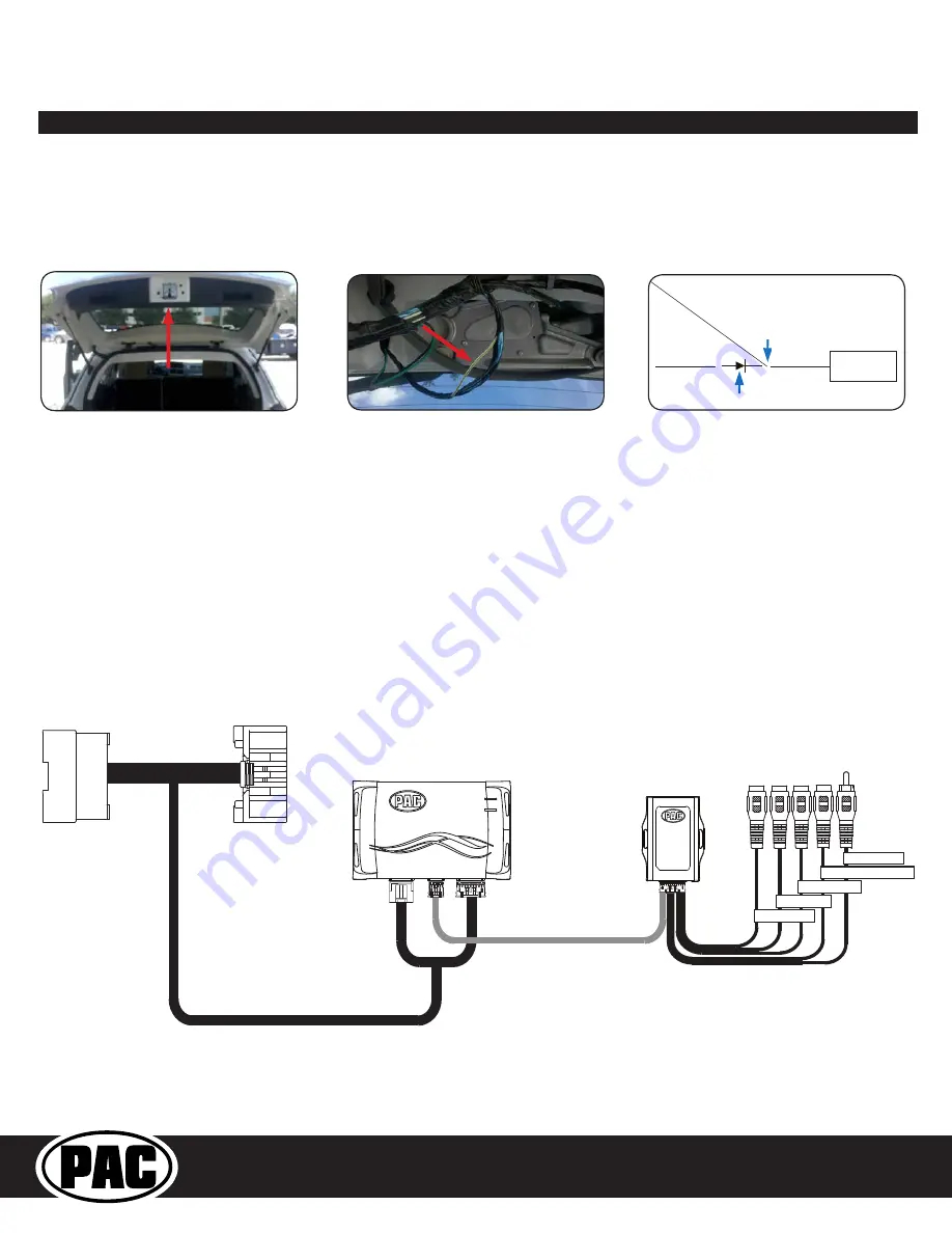
Connecting a VS41 (sold separately)

PLEASE NOTE: In order for the interface to support a VS41, the BCI must be programmed with firmware version 6 or higher.

If you are adding a front camera and two blind spot cameras, or any combination of the three, to the factory radio, a VS41 (sold separately) 

can be used in conjunction with the BCI. Follow the example below to make all inputs work accordingly through the one camera input on 

the factory radio. Connect the 10-pin harness from the VS41 harness into the Expansion Port on the BCI-CH21. Do not manually wire the 

trigger wires, or power and ground leads, when using the Expansion Port connector. When the appropriate CAN-Bus signals are detected (ie. 

reverse, or turn signal) the corresponding camera input will be automatically selected, and it’s video feed will be routed to the factory radio 

display. 

The behaviors of the cameras and output wires can be configured using the PAC app. Please see page 6 for full details on using the PAC app.

VIDEO OUTPUT

REVERSE CAMERA INPUT

FRONT CAMERA

LEFT CAMERA

RIGHT CAMERA

BCI-CH21-HAR

BCI-CH21

VS41

(Sold Separately)

To Radio

To Vehicle

Harness

Data controlled camera  

switching cable (10-pin)

Installation Steps (cont.) 

Reverse Camera Wire Location - Journey

1. You will need to locate the reverse camera wire in the reverse camera harness located in the liftgate. (Fig A).

2. The reverse camera wire is the White / Green wire (test with a DMM to verify 12v when the vehicle is shifted into reverse) (Fig B).

3. Connect programmable output 1 (10A, set to “Accessory” by default) from the BCI-CH21 harness to the White / Green wire using a diode

(Fig C). The diode is needed to prevent the reverse lights from coming on when the reverse camera is activated.

4. Verify that the reverse lights do not come on when the forced reverse camera / on-demand feature is activated.

Fig C

Reverse

Camera

Red C

amer

a A

ctiv

ation 

Wire

Wht/Grn Camera Wire

Connect Diode 

Here

Connect Red Wire

From BCI-CH21 Here

Fig A

Fig B

Содержание BCI-CH21

Страница 1: ...by the BCI CH21 on the multi function display MFD it must be set to display audio text 1 Turn on the dipswitches that correspond with the features you want to add These dipswitches must be set to the...

Страница 2: ...Dodge Caravan 2010 2015 Dodge Journey 2009 2010 Chrysler Town Country 2008 2015 Volkswagen Routan 2009 2013 Power Up Factory Reverse Camera 9 If you are adding an additional A V input Connect the A V...

Страница 3: ...nds and then release Activating the Forced Reverse Camera 1 Press and hold the Preset button on the SWC for at least two seconds and then release 2 The dash mount LED will begin blinking and the rearv...

Страница 4: ...le can tell you what the BCI CH21 is doing Please refer to the chart below for LED status patterns and possible troubleshooting actions VES Mode A V Harness LED Pattern State Action Dual flashing gree...

Страница 5: ...e the text generated by the BCI CH21 on the multi function display MFD it must be set to display audio text 1 Turn on the DIP switches that correspond with the features you want to add These dipswitch...

Страница 6: ...Year Dodge Caravan 2010 2015 Dodge Journey 2009 2010 Chrysler Town Country 2008 2015 Volkswagen Routan 2009 2013 Power Up Factory Reverse Camera 9 If you are adding an additional A V input Connect the...

Страница 7: ...mera 1 Press and hold the Preset button on the SWC for at least two seconds and then release 2 The dash mount LED will begin blinking and the rearview camera image will now display on the navigation s...

Страница 8: ...gle Flashing Red No CAN communication with vehicle Check harness and connector pins for proper connection LOAD MENU AUDIO PULL AUX HARD DISC DRIVE MP3 WMA JPEG VOLUME MEDIA RADIO PUSH ON RBZ MY FILES...

Страница 9: ...ombination of the three to the factory radio a VS41 is needed sold separately Follow the example below to make all inputs work accordingly through the one camera input on the factory radio Connect the...

Страница 10: ...o the factory radio display Data controlled camera switching cable 10 pin DISCLAIMER Under no circumstances shall the manufacture or the distributors of the BCI CH21 be held liable for claims of any l...

Страница 11: ...head unit You must use the factory A V input located in the rear of the vehicle 8 In order to see the text generated by the BCI CH21 on the multi function display MFD it must be set to display audio t...

Страница 12: ...s harness 13 Turn the ignition to the on position 14 Plug the 4 pin and 20 pin plugs on the BCI CH21 harness into interface connector 1 and 2 15 Both LEDs will blink green while the module is initiali...

Страница 13: ...the factory radio display The behaviors of the cameras and output wires can be configured using the PAC app Please see page 6 for full details on using the PAC app VIDEO OUTPUT REVERSE CAMERA INPUT F...

Страница 14: ...ly DIP switch 1 ON if adding rev cam OFF if already equipped DIP switch 2 User Preference DIP switch 3 OFF PC Settings Blind Spot Camera User Preference can t be OFF Front Camera Off Programmable Outp...

Страница 15: ...activate the BCI CH21 simply press and hold the Source button on the SWC for at least two seconds and then release or turn the radio off then back on again MP3 WMA JPEG VOLUME MEDIA RADIO PUSH ON Medi...

Страница 16: ...rive The camera input will turn off once the vehicles MPH is faster than 6MPH or after 30 seconds This mode will not work in vehicles with a manual transmission On when shift out of R until 6 MPH or 3...

Страница 17: ...u are receiving audio on only one side of the vehicle please make sure that the male pins in the BCI CH21 plug are not bent or out of place 5 The module can be reset to factory default settings by pre...

Отзывы: