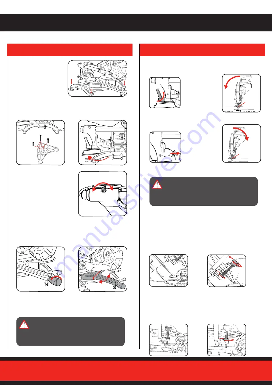
2. SET-UP AND ADJUSTMENTS
1. Loosen mitre
table lock
2. Rotate the mitre table to the
desired mitre angle (left or
right) as shown by the mitre
angle pointer
Mitre Angle Adjustment
MITRE ANGLE
POINTER
3. Tighten mitre table lock at selected angle
Bevel Angle Adjustment
3. Tighten bevel lock at selected angle
Note:
The mitre table features positive click stops at 0°, 15°, 22.5°,
31.6° and 45° for quick setting of common mitre angles.
Bench Mounting
The base of the saw has four
bench mounting holes (1 each
corner) that can be used to
mount it to a workbench or
mitre saw stand. Use four
screws or bolts (not included)
to secure.
WARNING!:
ENSURE THE MITRE TABLE LOCK
IS TIGHT BEFORE MAKING A CUT. FAILURE
TO DO SO MAY RESULT IN THE MITRE TABLE
MOVING DURING OPERATION AND CAUSE
SERIOUS PERSONAL INJURY.
WARNING!:
ENSURE THE BEVEL LOCK IS
TIGHT BEFORE MAKING A CUT. FAILURE TO
DO SO MAY RESULT IN THE CUTTING HEAD
MOVING DURING OPERATION AND CAUSE
SERIOUS PERSONAL INJURY.
Trenching refers to restricting the depth of cut and permits a “trench”
to be cut in the workpiece.
Bevel Angle Adjustment
Trenching
1. Ensure the cutting head is
raised, move the trenching
stop to the right as far as it
will go.
2. To adjust the trenching
depth rotate the trenching
depth adjustment screw.
3. To check that the blade
stops at the desired position,
lower the cutting head
until the trenching stop
adjustment screw touches
the trenching stop.
4. When the correct depth is
set. Lock it in position using
the trenching depth lock nut.
Slide Lock
When cutting a narrow piece of
wood it is not necessary to use
the slide mechanism. In these
circumstances, push back the
cutting head and ensure the slide
locking knob is tight to prevent the
cutting head from sliding.
To ensure the saw is standing securely when not mounting to a
workbench or mitre saw stand. Screw the Additional Support Feet
to the feet of the mitre saw with the fasteners provided. Then swing
out the Stabilising Bar to the rear until it engages.
18mm
18mm
30mm
1. Loosen bevel
lock.
2.
BEVEL LEFT
- Tilt the cutting head
to the desired
bevel angle
left as shown
by the bevel
angle pointer.
2a.
BEVEL RIGHT
- Tilt
the cutting head
slightly LEFT then pull
the bevel release.
BEVEL ANGLE
POINTER
BEVEL ANGLE
POINTER
2b. Tilt the cutting head to the desired
bevel angle right as shown by the
bevel angle
pointer.
BEVEL ANGLE
POINTER
BEVEL ANGLE
POINTER


