Releasing the Head Locking Pin
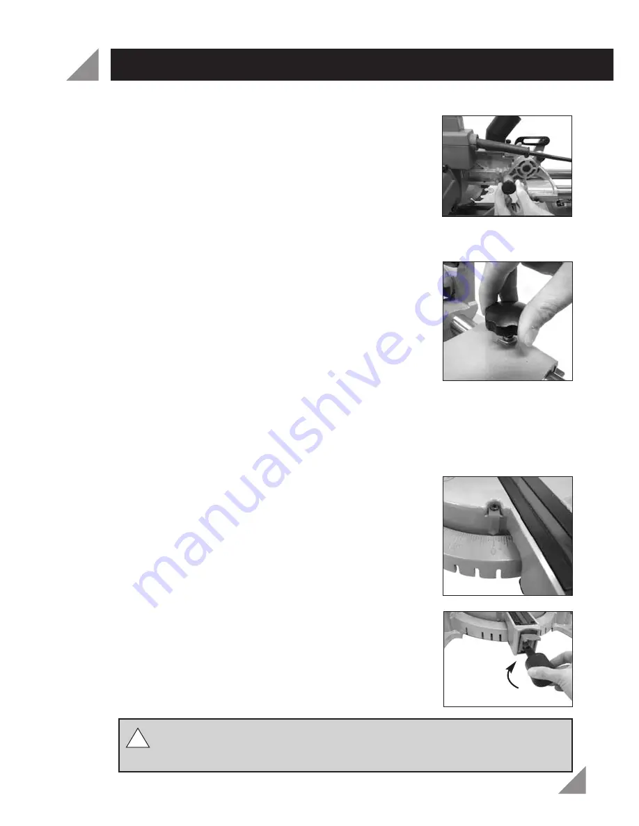
The head locking pin (4) is used to hold the cutting head (3)
down when transporting or storing the Mitre Saw. The Mitre
Saw must not be used with the cutting head (3) in the locked
down position.
1. To release the cutting head (3), push down on the top of
the cutting head (3), pull the head locking pin (4), rotate
it 90° (Fig. 4) and let go, gently raise the cutting head (3).
Locking the Slide Bars
When tightened, the slide locking knob (32) prevents the
slide bars (31) from sliding forwards and back. Tighten the
slide locking knob (32) (Fig. 5) during transportation or when
performing non-slide cross cuts.
1. To loosen the slide locking knob (32), turn in an anti-
clockwise direction.
2. To tighten the slide locking knob (32), turn in a
clockwise direction.
Adjusting the Mitre Angle
The mitre adjustment lever (27) is used to release the rotating mitre table (24) and
allows rotation to the required mitre angle. The mitre lock knob (26) is used to lock the
rotating mitre table (24) at the required mitre angle.
The Mitre Saw cuts from 0° to 45° both left and right and
features positive stops at 0°, 15°, 22.5°, 30° and 45° for quick
and accurate setting of common mitre angles. The mitre
angle indicator (28) shows what mitre angle the Mitre Saw is
set to (Fig. 6).
1. To fit the mitre lock knob (26), insert into the hole at the
front of the rotating mitre table (24) and rotate in a
clockwise direction (Fig. 7).
WARNING!
Ensure the mitre lock knob (26) is tight before making a cut. If it
is not secured, the table may move during operation and cause serious
personal injury.
SET-UP AND ADJUSTMENT (cont.)
10
Fig. 4
Fig. 5
Fig. 6
Fig. 7
!!


