background image

23

OPERATION (cont).

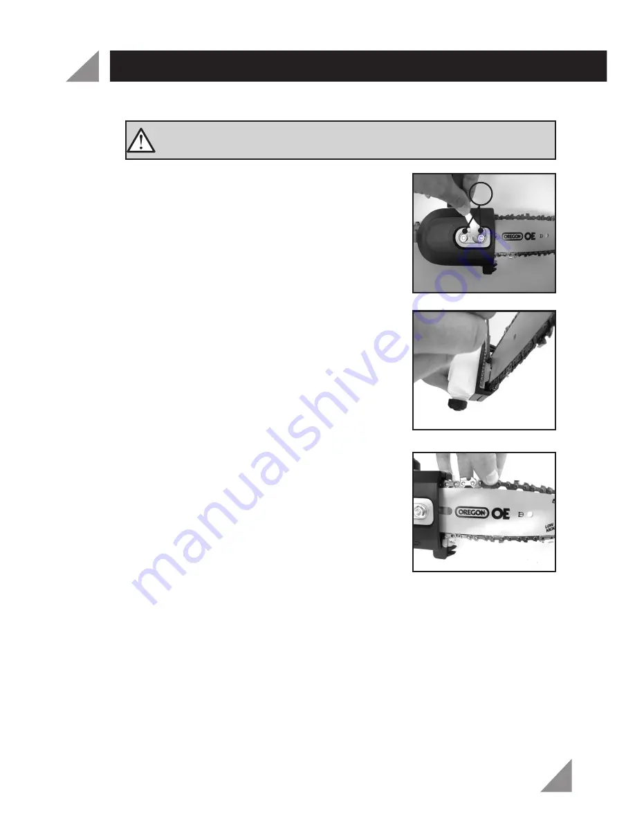
1.  Loosen the two chain drive cover nuts (c) 

with small open-end spanner (20) (Fig. 30). 

Caution:

 If you try to rotate the chain tension 

screw  whilst the chain drive nuts are tight, 

it will result in the chain not loosening and  

possible damage to the chain tensioning 

screw and the chain tensioning pin. 

2.  Turn the chain tensioning screw clockwise 

so that the chain is correctly tensioned 

(Fig. 31) 


3.  To get the correct chain tension, firmly 

pull up on the chain at the middle of the 

top of the exposed guide bar. When the 

chain is pulled up to its  highest point, 

the bottom tip of the links should only 

just stay in the track [middle of the guide 

bar] (Fig. 32). 

Fig.30

Fig.31

Fig. 32

Chain Tension 

4.  Once the correct tension has been achieved tighten the chain 

drive cover nuts to lock the bar and tension in place. 

5.  Check the tension again after a few minutes of cutting and 

several times in the first hour because the chain will lengthen as 

it breaks in. Adjust as you go. A loose chain causes rapid wear 

to both the chain and the guard bar and could derail causing a 

major safety hazard.

Note:

 Chains lengthen slightly as the link pins set into place. They 

set into place from the load applied to the chain, this process 

continues through-out the life of all chains as they gradually wear 

from use.

WARNING! 

The chain has sharp edges. For your safety, 

please use work gloves.

c

Содержание LT4-1000

Страница 1: ...y LT4 1000 WARNING Read all safety warnings and all instructions Failure to follow the warnings and instructions may result in electric shock fire and or serious injury Save all warnings and instructi...

Страница 2: ...ht 1 75kg Brush Cutter Blade 230 x 26mm Weight 1 85kg Note Line Trimmer Brush Cutter use the same shaft Pole Hedge Trimmer Attachment Blade length 370mm Cutting capacity 15mm 6 Position pivoting head...

Страница 3: ...ch Accessories 7 Safety guard 8 Safety guard extension for line trimmer 9 Shoulder strap 10 Brushcutter blade 11 Blade transport cover 12 Blade cover pruner 13 Spool set 7 8 9 11 12 13 10 14 15 16 17...

Страница 4: ...ARNINGS ADDITIONAL SAFETY WARNINGS FOR LINE TRIMMER BRUSHCUTTER HEDGE TRIMMER CHAINSAW PREPARATION SET UP OPERATION MAINTENANCE SPARE PARTS DESCRIPTION OF SYMBOLS PACK CONTENTS WARRANTY Page 2 Page 5...

Страница 5: ...ing from a possible electrical insulation failure within the tool Using an Extension Lead Always use an approved extension lead suitable for the power input of this tool Before use inspect the extensi...

Страница 6: ...r use Use of a cord suitable for outdoor use reduces the risk of electric shock f If operating a power tool in a damp location is unavoidable use a residual current device RCD protected supply Use of...

Страница 7: ...ories or storing power tools Such preventive safety measures reduce the risk of starting the power tool accidentally d Store idle power tools out of the reach of children and do not allow persons unfa...

Страница 8: ...eplace the extension lead if damaged or defective When using an extension lead on a reel always unwind the lead completely Use of an extension lead not suitable for the power input of the tool or whic...

Страница 9: ...the line trimmer out of the reach of children Face the cutting head away from yourself other people and animals while the power is connected to the line trimmer especially during operation Disconnect...

Страница 10: ...d by an authorized repairer Keep extension cord away from cutting blades Never allow children or people unfamiliar with these instructions to use the Pole Hedge Trimmer Avoid using the Pole Hedge Trim...

Страница 11: ...on while operating chain saws may cause entanglement of your clothing or body with the saw chain Always hold the chain saw with your right hand on the rear handle and your left hand on the front handl...

Страница 12: ...to keep your cutting jobs free from accident or injury Kickback is the result of tool misuse and or incorrect operating procedures or conditions and can be avoided by taking proper precautions as giv...

Страница 13: ...shaft attachment 3 Ensure the drive unit shaft locking button a clicks into the selected hole of the lower shaft attachment Fig 3 Note Gently pull the drive unit shaft to ensure the locking button a h...

Страница 14: ...d extension 8 for line trimmer use to the fitted safety guard 7 and secure using a phillips head screwdriver Fig 7 Fig 7 Assembling of spool set 13 1 Align the hole in the inner flange 14 with the hol...

Страница 15: ...screw the spool set 13 with the large open end spanner 20 turning clockwise Left hand thread Fig 11 Fig 11 Fig 10 Assembling of brush cutter blade 10 1 Align the hole in the inner flange 14 with hole...

Страница 16: ...move the blade transport cover 11 from the blade 10 before use by pulling in opposite directions from either side of the join Fig 15 Removing of brush cutter blade 10 1 Remove split pin 16 Align the h...

Страница 17: ...tart work unless the chain and bar are lubricated Fig 21 Note Check oil level regularly every 10 min during cutting to ensure the oil level in the tank does not fall below the MIN mark PREPARATION SET...

Страница 18: ...ndations for the use of a residual current device with a rated residual current of 30mA or less Children should be supervised to ensure that they don t play with the appliance OPERATION WARNING If cor...

Страница 19: ...s are achieved on dry grass Do not move the line trimmer brush cutter against the grass until the switch is pressed i e wait until the line trimmer is run ning before placing in grass For the correct...

Страница 20: ...hedge trimmer attachment to the drive unit tube Follow the instructions on page 13 Assembling drive unit to lower shaft attachment 2 Before starting the machine check that all parts are correct and t...

Страница 21: ...evel hedges To obtain exceptionally level hedges a piece of string can be stretched along the length of the hedge as a guide Fig 28 Side trimming hedges Hold the pole hedge trimmer and begin at the bo...

Страница 22: ...hain or bar is damaged do not continue to operate the pole pruner 1 Insert the pole pruner attachment to the drive unit tube Follow the instructions on page 13 Assembling drive unit to lower shaft att...

Страница 23: ...the links should only just stay in the track middle of the guide bar Fig 32 Fig 30 Fig 31 Fig 32 Chain Tension 4 Once the correct tension has been achieved tighten the chain drive cover nuts to lock t...

Страница 24: ...t be removed in one cut make an initial cut from the bent side and finish by sawing from the opposite direction Do not remove limbs that are supporting the fallen tree on the ground until the tree has...

Страница 25: ...tion out of the reach of children Replacing the spool line 1 With the line trimmer attachment upside down rotate the bump knob clockwise unlock position with the combination spanner 19 while holding t...

Страница 26: ...are no user serviceable parts in the Hedge Trimmer if a fault is suspected please contact Ozito customer service Pole Pruner Attachment The chain can be sharpened using a 5 32 size file A sharp chain...

Страница 27: ...he links should only just stay in the track middle of the guide bar Fig 43 6 Once the correct tension has been achieved tighten the chain drive cover nuts c to lock the bar and tension in place 7 Chec...

Страница 28: ...cutter SPLT4 10003086 Spool line trimmer SPLT4 1000307016 Carbon Brush Pair SPLT4 100010117 V Volts Hz Alternating current W min Revolutions or reciprocation per minute no Warning Wear ear protection...

Страница 29: ...PACK CONTENTS OZITO INDUSTRIES PTY LTD Power tools that are no longer usable should not be disposed of with household waste but in an environmentally friendly way Please recycle where facilities exist...

Страница 30: ...M UNDER THIS WARRANTY YOU MUST RETURN THE PRODUCT TO YOUR NEAREST BUNNINGS WAREHOUSE WITH YOUR BUNNINGS REGISTER RECEIPT PRIOR TO RETURNING YOUR PRODUCT FOR WARRANTY PLEASE TELEPHONE OUR CUSTOMER SERV...

Отзывы: