background image


Installation instructions 

PROTECTING THE FUTURE


Fig. 1.


Initial position of the leaves 


Содержание Praktika T-10

Страница 1: ...Installation instructions www oxgard com info oxgard com Tel 7 812 366 15 94 Full height turnstile Oxgard Praktika T 10 T 10H VOZROZHDENIE METALWORKS...

Страница 2: ...PROTECTING THE FUTURE...

Страница 3: ...ry equipment 13 4 2 Installation of the turnstile 14 5 Connection of the turnstile 25 5 1 Connection of the control board 28 5 2 Connection of the access control system optionally 29 5 3 Connection of...

Страница 4: ...Oxgard Praktika 10 T 10H 4 List of abbreviations used PSU power supply unit S FA security and fire alarm CB control board ACS access control system NC normally closed NO normally opened Turnstile fir...

Страница 5: ...per minute 20 Service life year 8 8 Table 2 Electrical data Parameter Turnstile Console Power supply voltage V 220 12 0 Rated consumption power W 75 values are given for the rated power supply voltage...

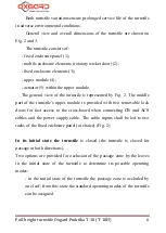
Страница 6: ...g 2 The middle part of the turnstile s upper module is provided with two removable lock doors for fast access to the cross board when connecting CB and ACS cables and the power supply cable The cable...

Страница 7: ...Installation instructions 7 PROTECTING THE FUTURE Fig 1 Initial position of the leaves...

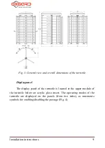
Страница 8: ...Full height turnstile Oxgard Praktika 10 T 10H 8 PROTECTING THE FUTURE Fig 2 General view of the turnstile...

Страница 9: ...ons of the turnstile Display panel The display panel of the turnstile is located at the upper module of the turnstile below an acrylic glass insert The operating modes of the turnstile are displayed o...

Страница 10: ...ns and LED indicators for desk operation modes Fig 5 The standard length of the cable included in the scope of supply is 10 meters The control board cable is laid in the body of the upper module 4 Fig...

Страница 11: ...onditions not complying with the requirements to operating conditions operate the turnstile under power supply voltage different from that specified in Table 2 When maintaining the turnstile All the w...

Страница 12: ...djustable climatic conditions The control board can be operated at ambient temperature between 1 to 55 and relative air humidity up to 80 at the temperature 25 CAUTION Non observance of the requiremen...

Страница 13: ...take measures to reinforce the floors in the place of installation Carefully study the present section of the Instructions before starting to check the operability 4 1 Necessary equipment Equipment t...

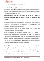
Страница 14: ...uidelines from the installation drawing Fig 20 mark the location for boring by means of a pattern 4 2 4 According to the installation dimensions Fig 21 prepare 9 openings with 18 mm diameter in a floo...

Страница 15: ...ntrol and power supply of the turnstile will be laid to the upper module Prepare the cable channel from the site to the installation location of the CB and if required to the place of connection of AC...

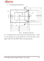
Страница 16: ...E FUTURE accompanying documentation Fig 6 Installation dimensions 4 2 8 Assemble the fixe enclosure panel of the turnstile of Fig 7 Install it on the prepared site by pre passing into its rack CB cabl...

Страница 17: ...3 4 Plug 30 33T38 K 5 Washer 12 DIN 125 6 Washer 12 DIN 127 7 Nut 12 Fig 7 Assembly of the fixed enclosure panel 4 2 9 Fix the fixed enclosure panel of the turnstile with the clamps 1 2 pcs and centra...

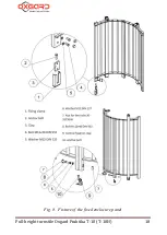
Страница 18: ...Full height turnstile Oxgard Praktika 10 T 10H 18 PROTECTING THE FUTURE Fig 8 Fixture of the fixed enclosure panel...

Страница 19: ...0 Install and fix the fixed enclosure element of the turnstile with the anchors Fig 9 by screwing them into respective openings by means of the 19 mm key Install plastic caps onto heads of the fixture...

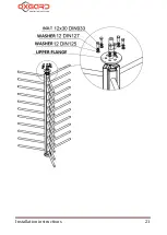
Страница 20: ...20 PROTECTING THE FUTURE 4 2 11 Assemble the mobile elements of the turnstile rotatory wicket door of Fig 10 Turn the sections of the wicket door so as h upper h lower Place the rotor sections onto th...

Страница 21: ...Installation instructions 21 PROTECTING THE FUTURE...

Страница 22: ...ket door 4 2 12 Install the upper module of the turnstile onto the fixed enclosure elements by pre passing the cables into the respective holes Fix the upper module by fixing bolts of Fig 11 and 12 At...

Страница 23: ...nstallation instructions 23 PROTECTING THE FUTURE 1 Bolt 12 30 DIN 933 2 Washer 12 DIN 127 3 Washer 12 DIN 125 4 Nut 12 DIN 934 5 Clap for nut 12 Fig 11 Attachment of the upper module of the turnstile...

Страница 24: ...125 5 Clap for nut 12 Fig 12 Attachment of the second fixed enclosure element 4 2 13 Install the fluoroplastic bushing onto the lower axle install the rotatory wicket door onto the lower axle of the...

Страница 25: ...the upper cover are located internally of the cover Fig 13 Fixture of the upper cover 5 Connection of the turnstile The cables shall be led through a hole made in the rack of the fixed enclosure panel...

Страница 26: ...Full height turnstile Oxgard Praktika 10 T 10H 26 PROTECTING THE FUTURE Fig 14 220 V 12 V...

Страница 27: ...upper module of the turnstile Check if the cables are reliably connected Install the doors and lock them Fig 15 Arrangement of the cross board on the upper module of the turnstile Fig 16 shows extern...

Страница 28: ...d and the status of the buttons is transmitted to the outputs I O1 I O4 see item 5 4 J2 removed The turnstile is controlled by the board and the status of the buttons is transmitted to the outputs I O...

Страница 29: ...nals Access Control System at the cross board The terminals are marked as LEFT RIGHT STOP AP GND The terminals are designated according to Table 5 Table 5 Designation of ACS terminals Labeling of the...

Страница 30: ...lly switched into the mode Stop after 5 seconds CAUTION If one of inputs STOP and or AP is closed the commands from the board are not accepted as ACS is assigned with a higher priority The inputs STOP...

Страница 31: ...PassOk1 meaning to right and PassOk2 meaning to left The cross board is designed with a relay output for ACS which operates under the dry contact principle namely Status NO and COMM means normally ope...

Страница 32: ...agram for connecting the turnstile it is necessary to install the jumper J2 onto the cross board Fig 16 If the jumper J2 is installed the turnstile is not responding to commands by the board but just...

Страница 33: ...anic 4 Fig 17 The outputs I O1 I O3 display a current status of the CB buttons i e the transistor shall open when pressing the respective button The output I O4 is reversed in its status when pressing...

Страница 34: ...the contact Antipanic is switched on off by the board An important feature for connecting the CB via the ACS controller is that it is impossible to use turnstile modes which are set by combinations of...

Страница 35: ...12 V 100 mA power supply unit can be installed at the place where the control board is installed with minimum operating power supply voltage to CB equal to 7 5 V In this situation 3 wires from the tu...

Страница 36: ...0 T 10H 36 PROTECTING THE FUTURE Appendix 2 Arrangement of the installation openings relative to the external dimensions of the turnstile Fig 20 Arrangement of the installation openings relative to th...

Страница 37: ...Installation instructions 37 PROTECTING THE FUTURE Fig 21 Sample for turnstile installation...

Страница 38: ...Full height turnstile Oxgard Praktika 10 T 10H 38 PROTECTING THE FUTURE Fig 22 Turnstile installation dimensions...

Страница 39: ...Installation instructions 39 PROTECTING THE FUTURE...

Страница 40: ...Vozrozhdenie LLC 192289 Saint Petersburg 66 Sophiyskaya St Tel fax 7 812 336 15 94 www oxgard com info oxgard com VOZROZHDENIE METALWORKS...

Отзывы:

Похожие инструкции для Praktika T-10