background image

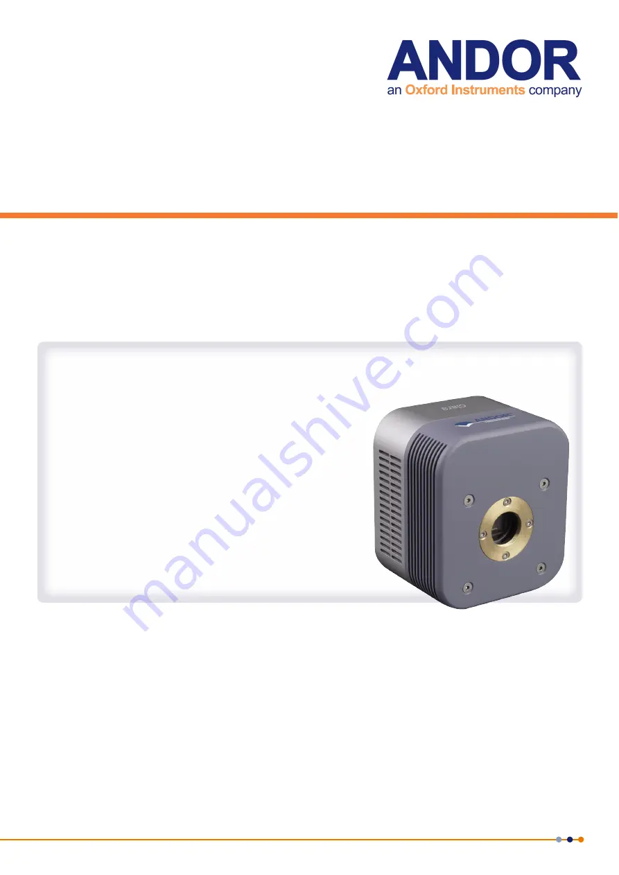
Clara

Version 2.0 rev 24 Mar 2015

Hardware Guide

andor.com

© Andor Technology 2015

Содержание ANDOR Clara

Страница 1: ...Clara Version 2 0 rev 24 Mar 2015 Hardware Guide andor com Andor Technology 2015...

Страница 2: ...ow 11 2 1 3 C Mount 11 2 1 4 Cooling Slots 11 2 2 REAR PANEL 12 2 2 1 USB 2 0 Connection 12 2 2 2 Cooling Fan 12 2 2 3 Multi I O Timing Cable Connection 12 2 2 3 1 Multi I O Timing Cable Pin Outs 12 2...

Страница 3: ...PARAMETERS 20 4 6 1 Using Shutters 20 4 6 2 Time to Open or Close 21 4 6 3 Exposure Time 22 4 6 4 Accumulate Cycle Time No of Accumulations 23 4 6 5 Kinetic Series Length Kinetic Cycle time 23 SECTIO...

Страница 4: ...2 0 rev 24 Mar 2015 SECTION 7 SPECIFICATIONS 26 7 1 CAMERA TECHNICAL SPECIFICATIONS 26 7 2 CAMERA 26 7 3 ENVIRONMENTAL 27 APPENDIX A GLOSSARY 28 APPENDIX B MECHANICAL DRAWINGS 38 APPENDIX C OTHER INFO...

Страница 5: ...refore should not be used or stored close to EMI RFI generators electrostatic field generators electromagnetic or radioactive devices or other similar sources of high energy fields 12 Operation of the...

Страница 6: ...s throughout all sections Improved description of camera hardware Section 2 Removal of Solis software content obsolete replicated information This is covered in full in the Solis in application help S...

Страница 7: ...The Clara is controlled through control software such as Andor Solis Please refer to the software guide supplied with your software for further information 1 1 Help and Technical Support When the app...

Страница 8: ...apan 4F NE Sarugakucho Building 2 7 6 Sarugaku Cho Chiyoda Ku Tokyo 101 0064 Japan Tel 81 3 3518 6488 Fax 81 3 3518 6489 USA Andor Technology 425 Sullivan Avenue Suite 3 South Windsor CT 06074 USA Tel...

Страница 9: ...CES The copyright in this document and the associated drawings are the property of Andor Technology and all rights are reserved This document and the associated drawings are issued on condition that t...

Страница 10: ...onal and additional accessories available for your Clara camera including Mounting Flanges Multi I O cable options Extension tubes Software Solis SDK and iQ Please contact Andor or your nearest Andor...

Страница 11: ...elimination of dark current 2 1 2 Camera Window A single camera window protects the sensor and is part of the UltraVac system refer to the Appendix in this manual for further information 2 1 3 C Moun...

Страница 12: ...CCD Sensor Refer to Appendix A 2 2 3 Multi I O Timing Cable Connection The multi I O connection enables interconnection control and synchronisation between a range of devices Pin out information is pr...

Страница 13: ...era is powered up Maximum current which can be drawn is 500mA I O bits 8 off are user programmable and can either be inputs or outputs When being used as inputs these default to being weakly pulled hi...

Страница 14: ...they do so at their own risk 2 2 7 Power Connection Pin outs A 4 pin power connector is fitted for power connection details are shown below Figure 6 Left Camera Connection Tyco Electronics Part 6 143...

Страница 15: ...ositioned so that the mains supply plug cord can be easily accessed for disconnection 3 2 Mounting Instructions To prevent damage to the Clara other equipment and or personnel the camera must be secur...

Страница 16: ...SDK NOTE You must have administrator access on your PC to perform this installation The same instructions cover the installation procedure for Andor s Solis software or Andor s SDK which is used in c...

Страница 17: ...he PC 2 Power up the camera ensuring that power is ON at the mains power socket 3 Turn ON the rocker switch on the rear panel of the Clara 4 Launch the camera control software e g Solis 4 3 Power down...

Страница 18: ...ure READOUT MODE Image Multi Track FVB Full Vertical Binning HORIZONTAL PIXEL SHIFT READOUT RATE 1MHz at 16 bit 10MHz at 14 bit 20MHz at 14 bit HORIZONTAL PIXEL SHIFT PRE AMPLIFIER GAIN 1x 2x MODE Nor...

Страница 19: ...For this mode to become fully active requires the first 1mS of the exposure so it is not recommended for exposures of less than 10 mS In this mode the amplifier is also powered down during the acquis...

Страница 20: ...ckground shuttering Certain settings e g Permanently OPEN Permanently CLOSED take effect as soon as you close the Shutter Control dialog box Other settings will be applied whenever you acquire data Fu...

Страница 21: ...the system will cause the output voltage from the Clara to go high to open the shutter The documentation supplied by the shutter manufacturer will show whether your shutter opens at a high or a low T...

Страница 22: ...Setting the Time to open or close to any other value will insert extra delays into cycle time calculations Figure 9 Example Illustration of Signals and delays for a typical Shutter 4 6 3 Exposure Time...

Страница 23: ...ans whose data are to be added together in computer memory to form an Accumulated Scan The Number of Accumulations indicates the number of scans you want to add together 4 6 5 Kinetic Series Length Ki...

Страница 24: ...ctors Use water only do not use solvents cleaning agents or aerosols 5 2 Regular Checks The state of the product should be checked regularly especially the integrity of the External Power Supply and t...

Страница 25: ...erature condition has occurred within the camera Follow the instructions below to rectify this situation 1 Power the camera off and allow it to cool down 2 Ensure fan vents are not obstructed 3 Check...

Страница 26: ...Better than 99 Dual digitization 16 bit 1 MHz 14 bit 10 MHz 20 MHz Baseline bias offset clamp Yes Timestamp accuracy 12 5 ns System window type UV grade fused silica Broadband VUV NIR unwedged 7 2 Ca...

Страница 27: ...ated supply that would be experienced by any product connected to a mains socket in a building Rated Pollution Pollution Degree 2 Normally only non conductive pollution occurs Occasionally however a t...

Страница 28: ...number of pixels as a light collecting row but is itself masked so that no light can fall on it When light falls on an element electrons photoelectrons are produced and in normal operation these elec...

Страница 29: ...ion of the readout sequence of a CCD 1 Exposure to light causes a pattern of charge an electronic image to build up on the frame or image area of the CCD chip 2 Charge in the frame is shifted vertical...

Страница 30: ...Figure 12 Image is acquired in the active pixels Figure 13 Image is shifted behind the masked region in one simultaneous horizontal shift Once complete acquisition of the next image can begin Figure...

Страница 31: ...d is a data acquisition made in darkness It is made up of fixed pattern noise and any signal due to dark current Binning Binning is a process that allows charge from two or more pixels to be combined...

Страница 32: ...e from each complete column of pixels on the CCD is moved down and summed into the shift register and the charge is then shifted horizontally one pixel at a time from the shift register into the outpu...

Страница 33: ...then charge from two pixels of the shift register is binned horizontally into the output node of the amplifier The effect of the combined binning processes is a summed charge equating to a 2 x 2 super...

Страница 34: ...D reduces dark signal typically for every 7 C that temperature falls dark signal halves CCD readout noise is low and so as not to compromise this by shot noise from the dark signal it is important to...

Страница 35: ...ic physical laws Most simply defined shot noise is the square root of the signal or dark signal measured in electrons Readout Noise Readout noise which in our cameras is in any case low is due to the...

Страница 36: ...fers to signals as a number of electrons More strictly speaking these are photoelectrons created when a photon is absorbed When a UV or visible photon is absorbed by the CCD detector it can at best pr...

Страница 37: ...dout above In this User s Guide scan generally refers to an acquired scan unless the context specifically indicates otherwise Signal to Noise Ratio The Signal to Noise Ratio commonly abbreviated as S...

Страница 38: ...Clara 38 Version 2 0 rev 24 Mar 2015 APPENDIX B MECHANICAL DRAWINGS Dimensions in mm inches Front and side view Focal Plane Distance Mounting Hole locations MECHANICAL DRAWINGS...

Страница 39: ...luding warranty conditions will have been made available during the ordering process The current version may be viewed at http www andor com pdfs literature Andor_Standard_Warranty pdf Waste Electroni...

Отзывы: