


__________________________________________________________________________________
__________________________________________________________________________
IPU 40285 Version E Jan 2013
13
Offset:
The output from the detector is converted into a 16 bit number. The full range of the
output is very approximately equivalent to +250°C to -50°C.
Note: The unit is not calibrated.
Minimum offset: -32768. Equivalent to the lowest temperature.
Maximum offset : 32767 Equivalent to the highest temperature.
Note: Please use this with caution and we recommend trial to get the optimum result. In
addition on a shutter the values and the display can shift
.
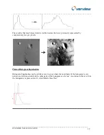
7.1.2 Histogram.
Four histogram settings are available. As the histogram mode operates on the temperature
histogram of the scene, the choices provide different weighting factors to the histogram.
Allowing more weighting to either the colours in the middle of the temperature range or to
the colours at the outer ends of the range.
7.2.
Temporal filter: Can be set between 0 to 8. This is the number of frames over which the
auto gain operates. Hence a fleeting event can be ignored.
7.3
Spatial filter: Number of pixels which must see the maximum or minimum temperature for
inclusion in the gain calculations.
7.4. Tracking.
When tracking is selected, a green box tracks the highest temperature pixel. If there is a
requirement to restrict this to part of the scene the track box numbers can be used to define and
restrict the tracking area.
7.5.
Rotate
Allows the user to flip the image. Useful when the core is mounted in another housing. For e.g. if
the housing is ceiling mounted, the image will need to be flipped to be the right way up.
7.6.
Power-up mode
Allows the user to set the camera to switch on up when the power supply is plugged in. This is the
default mode. If start in “standby” is selected then the camera does not switch on when the power
supply is plugged in. The user then has to send a command to switch the camera on.
7.7.
RS485 Bus settings
It is possible to daisy chain up to 16 cameras on a single RS485 bus. This allows the setting of
addresses to each camera. Also in this instance the termination camera needs to be defined.
7.8.
User text
Allows the user to add text to multiple cameras to identify the data coming back more easily. For
e.g. “Car Park”.
7.9.
Camera Baud rate
Allows the user to change the baud rate used to communicate with the camera. The camera has
to be power cycled and the software has to be restarted to take effect.


