10400287-002 03/2011
©2010-11 Overland Storage, Inc.
Page 5 of 7
Quick Start Guide
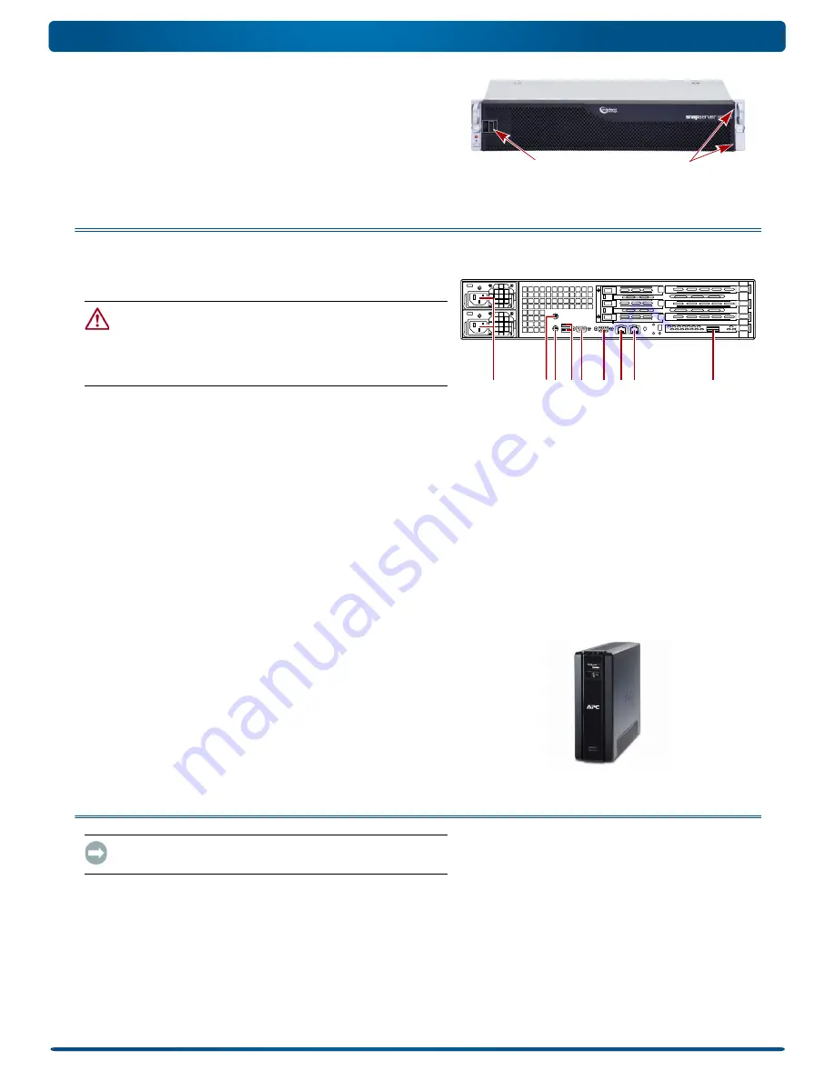
Attach the Bezel
1.
Insert the
right bezel pins
into the chassis right flange.
2.
Push the
latch
in (toward the bezel center) and press the
bezel into place against the drives.
3.
Release the latch so that the
left pins
fit in the left flange.
Step 4: Attach Cables and Power Cords
All cabling and power connections are located on the rear panel of
the SnapServer N2000. All unit cooling exhaust is handled
through the rear panel.
CAUTION:
The speed/duplex setting on N2000 servers defaults
to autonegotiate. The networking switch or hub to which the
server is connected must also be configured to autonegotiate;
otherwise, network throughput or connectivity to the server may be
seriously impacted.
1.
Plug the
network connection
into Ethernet1 port.
Using a Category 5e (or better) cable, connect
Ethernet1
port on the server to a Gigabit Ethernet switch on the same
LAN as the management system.
NOTE: To take advantage of network bonding (load balancing or
failover), both data ports must be physically connected to the
network. For load balancing, connect them to the same switch on
the same subnet with the switch set to auto-negotiate. For failover,
connect them to different switches on the same subnet.
2.
Connect any SanDisk E2000 expansion arrays using the
instructions that came with the units.
3.
Attach the power cords to the
AC Power
sockets.
4.
Plug the
power cords
into a UPS appliance or a properly
grounded AC power source.
NOTE: SnapServer systems are designed to work with APC-brand
USB or network-based UPS devices to automatically shut down
cleanly in the event of a power failure. You must configure the APC
unit both in the SnapServer’s Web Management Interface and in
the APC user interface.
Step 5: Initial Power Up
IMPORTANT: To properly initialize the server for use, power it ON
without powering ON any attached expansion units.
1.
Turn the N2000 server
ON
by pressing and holding the
Power button for no more than one (1) second.
The System LED blinks green once per second. The first-time
self configuration takes a few minutes.
Latch
Pins
1 - AC Power
2 - Mouse Port*
3 - Keyboard Port*
4 - Dual USB Ports
5 - Serial Port*
6 - Video Port*
7 - Ethernet1 Port
8 - Ethernet2 Port
9 - SAS Port
1
2
4 5
6 7 8
9
3
*
Unsupported for the SnapServer N2000.


