oventrop Regtronic RX Скачать руководство пользователя страница 9

en

9

3.2.1  Adjusting the timer 

When the 

Timer 

option is activated, a timer is in-

dicated in which time frames for the function can be 
adjusted.
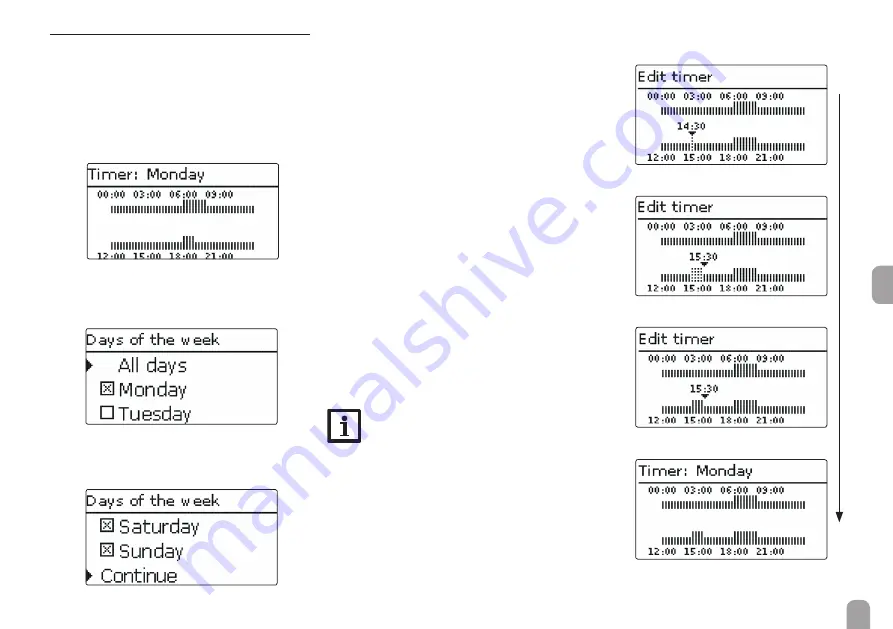
First of all, an overview of the current adjustments is 
displayed. For each day of the week there is an over-
view display. The display can be switched back and 
forth between the different days by pressing buttons 

 or 

In order to adjust the timer, press button 

First, individual or all days of the week can be selected 
for timer adjustment.

The last menu item after the list of days is 

Continue

If Continue is selected, the 

Edit timer

 menu opens, 

in which the time frames can be adjusted.

Adding a time frame:

The time frames can be adjusted in steps of 15 min. 
In order to add an active time frame, proceed as fol-
lows:


Î

Move the cursor to the desired starting point of 
the time frame by pressing buttons 

 and 

Confirm the starting point of the time frame by 
pressing button 

.


Î

Move the cursor to the desired ending point of 
the time frame by pressing buttons 

 and 


Î

The end of a time frame can be determined by 
pressing button 

.


Î

In order to add another time frame, repeat the 
last three steps.

Note:

In order to adjust a 24 h time frame, press 
button 

 once during the adjustment pro-

cess.


Î

Press button 

 again to get back to the overview 

of current adjustments.

Содержание Regtronic RX

Страница 1: ...to Le istruzioni complete sono disponibili nel seguente link www oventrop com http www oventrop de qr 136109581 IT ES Instrucciones de instalaci n y opera ci n para el instalador especializado El manu...

Страница 2: ...to technical change Errors excepted Target group These instructions are exclusively addressed to au thorised skilled personnel Only qualified electricians should carry out electrical works Initial in...

Страница 3: ...on 14 4 3 SD card slot 17 5 Step by step parameterisation 17 5 1 Menu structure 18 6 Status 19 6 1 Solar 19 6 2 Arrangement 19 6 3 Messages 19 6 4 Meas Balance values 19 6 5 Service 19 7 Solar 20 7 1...

Страница 4: ...layers priority logic heat dump function circulation function PWM pump con trol function control Inputs 8 9 inputs for Pt1000 Pt500 or KTY tem perature sensors 7 of them can be used for remote control...

Страница 5: ...r fastening points centres 150mm Insert lower wall plugs Fasten the housing to the wall with the lower fas tening screw and tighten Carry out the electrical wiring in accordance with the terminal allo...

Страница 6: ...Bus GND 1 PWM output 1 control signal 2 PWM output 1 GND 3 PWM output 2 GND 4 PWM output 2 control signal In the In Outputs menu relays can be allocated to the PWM outputs Connect the digital Grundfos...

Страница 7: ...sed for a few seconds the display illumination goes out Press any key to reactivate the display illumination In order to scroll though a menu or to adjust a value press either buttons and or buttons a...

Страница 8: ...aved minimum value maximum value adjusted value not yet confirmed adjustment channel When 2 values are locked against each other they will display a reduced adjustment range depending on the adjustmen...

Страница 9: ...tinue is selected the Edit timer menu opens in which the time frames can be adjusted Adding a time frame The time frames can be adjusted in steps of 15 min In order to add an active time frame proceed...

Страница 10: ...me is to be removed by pressing button Move the cursor to the desired ending point of the time frame by pressing buttons and In order to conclude removing the time frame press button upon reaching the...

Страница 11: ...n it is reset it will run a commissioning menu after the initialisation phase The commissioning menu leads the user through the most important ad justment channels needed for operating the system Comm...

Страница 12: ...enquiry appears If the security enquiry is confirmed the ad justments are saved In order to confirm the security enquiry press button In order to reenter the commissioning menu channels press button I...

Страница 13: ...stem 1 1 collector field 1 store System 2 1 collector field 1 store with store loading in layers System 3 1 collector field 2 stores System 4 east west collectors 1 store System 5 east west collectors...

Страница 14: ...unction Sensor Collector Primary circuit Secondary circuit Store base Free Store top Free Free Free System 2 S2 S3 S4 S6 R2 R4 VFD S5 R1 S1 C o l St top St base St centre Relay sensor allocation 1 2 3...

Страница 15: ...Collector pump Secondary circuit Optional function 3 port valve Optional function Sensor Collector Primary circuit Secondary circuit Store 1 base Free Store 1 top Store 2 base Store 2 top Free 1 2 3...

Страница 16: ...r pump 1 Secondary circuit Collector pump 2 3 port valve Optional function Sensor Collector 1 Primary circuit Secondary circuit Store base Store centre Store top Collector 2 Free Free 1 2 3 4 5 6 7 8...

Страница 17: ...urther information about the commissioning menu see page 11 2 Registering sensors If impulse flowmeters Grundfos Direct Sensors and or external extension modules are connected these have to be registe...

Страница 18: ...Loading logic HX Load in layers Blocking protection Opt functions Afterheating Return preheating Solid fuel boiler Circulation Error relay Function block Parallel relay The menu items and adjustment v...

Страница 19: ...yed Some of the menu items can be selected in order to enter a sub menu Additionally all optional functions selected the oper ating hours counter as well as activated heat quantity measurements are di...

Страница 20: ...made in the non solar function will be set back to their factory settings as well Collector 1 2 In systems with 2 collector fields 2 seperate menu items Collector 1 and Collector 2 are displayed inste...

Страница 21: ...es first according to their priority and the store sequence control Only if all stores have exceeded Stset will they be loaded up to their Stmax temperatures again according to their priority and the...

Страница 22: ...freeze function When the temperature at the reference sensor ext HX S2 falls below the non adjustable antifreeze temperature 10 C the controller will activate the secondary pump at 100 speed The antif...

Страница 23: ...ing Adjustment channel Description Adjustment range selection Factory setting Target temp Target temperature 15 85 C 59 C DTon Store loading in layers switch on difference 1 0 20 5K 5 0K DToff Store l...

Страница 24: ...loading pro cess stops and the controller monitors the increase in collector temperature during the loading break time Load break If it increases by 2K the break time starts again to allow the collect...

Страница 25: ...ion are available With the menu item Function an optional func tion already selected can be temporarily deactivated or re activated respectively All adjustments remain stored the allocated relays rema...

Страница 26: ...pump the control ler will automatically switch to solar loading In the Delay channel a switch on delay for the pump can be adjusted This ensures that e g a check valve in the collector circuit has com...

Страница 27: ...he virtual relay Demand in the Arrangement Opt functions AH suppress Relay channel The afterheating will then only demand heat from the boiler when the store temperature falls be low the switch on tem...

Страница 28: ...ollector maximum temperature is exceeded Store loading continues until all stores have reached the emergency shutdown temperature or until the collector temperature falls below the collector maxi mum...

Страница 29: ...40 120 C 120 C Funct Activation Deactivation Activ Deactivated Activated Solar opt functions Add new function Heat dump Adjustment channel Description Adjustment range selection Factory setting Varia...

Страница 30: ...tion Adjustment range selection Factory setting Overload protection Overloading protection Yes No Yes Emergency temperature Emergency temperature 60 95 C 90 C SFB Off Solid fuel boiler off Yes No No S...

Страница 31: ...splayed in corresponding sub menus When a new function is activated the next free sen sor inputs will automatically be allocated in a numer ical order This allocation can be changed at any time When a...

Страница 32: ...zone if necessary It works independently from solar loading and can be activated by the user As soon as the temperature at the allocated store ref erence sensor falls below the switch on temperature...

Страница 33: ...ion of 2K the pump speed will be adjusted by 10 Adjustment channel Description Adjustment range selection Factory setting Relay Relay selection system dependent system dependent Sen Boiler Solid fuel...

Страница 34: ...ted The time frames can be adjusted in steps of 15 min By pressing buttons or the cursor can be moved along the time line Select the starting point of the time frame by pressing button The end of a ti...

Страница 35: ...utside the heating period Adjustment channel Description Adjustment range selection Factory setting Relay Relay selection system dependent system dependent Sen Return Return sensor selection system de...

Страница 36: ...n The relay allocated to the function block is switched on as soon as the adjusted switch on temperature difference T x on is reached It is switched off as soon as the adjusted switch off temperature...

Страница 37: ...Switch off temperature Thermostat b 40 250 C 45 C Sensor Sensor thermostat b system dependent system dependent DT function Differential function Yes No No Ton Switch on temperature difference 1 0 50 0...

Страница 38: ...o is indicated in which the antifreeze ratio of the heat transfer fluid can be adjusted When the Alternative unit is activated the control ler will convert the heat quantity into the quantity of fossi...

Страница 39: ...99 01 01 2010 Time Adjustment of the current time 00 00 23 59 Temp Unit Temperature unit C F Vol Unit Volume unit Gallons Liter Press Unit Pressure unit psi bar Energy Unit Energy unit Wh kWh BTU Fact...

Страница 40: ...first Please wait then Done will be indicated on the display Formatting the SD card Select the menu item Format card The content of the card will be deleted and the card will be formatted with the FA...

Страница 41: ...for the controller relays Auto Off Auto Module 1 5 Relay 1 5 Operating mode selection for the relays of modules connected Max Auto Min Off Auto Manual mode The operating mode can be selected for each...

Страница 42: ...on Modules In outputs Modules 14 1 Modules In this submenu up to 5 Extension Modules Regtronic EM Oventrop Article no 1152098 can be registered All modules connected and acknowledged by the con trolle...

Страница 43: ...djustment range selection Factory setting S1 S8 Sensor input selection Type Selecting the sensor type Switch KTY Pt500 RTA11M Pt1000 None Pt1000 Offset Sensor offset 15 0 15 0K 0 0K CS10 CS10 input Ty...

Страница 44: ...p is effected The following modes are available Adapter speed control signal via a S Bus PWM interface adapter 0 10V speed control via a 0 10V signal PWM speed control via a PWM signal Standard burst...

Страница 45: ...d R1 R2 PWM R3 Adapter Output PWM output selection 6 7 Profile PWM curve A B C D E F D Min speed Minimum speed 20 100 30 Mo 1 5 R 1 5 Signal Signal type Adapter 0 10V PWM Standard Standard Output PWM...

Страница 46: ...M B e g manufacturer Grundfos 100 90 80 70 60 50 40 30 20 10 0 0 5 10 15 20 25 30 35 40 45 50 55 60 65 70 75 80 85 90 95 100 Solar PM Profile PWM PWM C e g manufacturer Laing 20 No PWM RPM Max rpm Min...

Страница 47: ...t be adjusted in order for the pump to work at a minimum speed 25 PWM E e g manufacturer Grundfos 100 95 90 85 80 75 70 65 60 55 50 45 40 35 30 25 20 15 10 5 0 0 10 20 30 40 50 60 70 80 90 100 OEM STA...

Страница 48: ...it The fuse of the controller could be blown The fuse becomes accessible when the cover is removed The fuse can then be replaced Check the power supply of the controller Is it disconnected no yes C F...

Страница 49: ...calcified yes Check replace it Decalcify it no Heat exchanger blocked Heat transfer fluid has aged yes yes no no no Clean it Replace heat transfer fluid Air inside the system yes yes Change Ton and To...

Страница 50: ...outdoor temper ature no yes Controller might be defective replace it Is the pump stuck Dismount the pump and turn the pump shaft using a screwdriver now passable Pump is defective replace it yes no D...

Страница 51: ...38 Holiday function 28 L Loading controller adjustments 40 M Mains connection 6 Manual mode 41 Maximum store temperature 21 Measured values 19 Minimum collector limitation 20 Modules registration of...

Страница 52: ...notice 136109582 04 2016 OVENTROP GmbH Co KG Paul Oventrop Stra e 1 D 59939 Olsberg Telephone 49 0 296282 0 Fax 49 0 296282 400 E mail mail oventrop de Internet www oventrop com For an overview of ou...

Отзывы: