background image

Multidis SFQ 

General information

1.  General information

The original operating instructions are written 
in German.
The operating instructions in other languages 
have been translated from German.

1.1 

Validity of the operating 

instructions

These operating instructions are valid for the 
Multidis SFQ heating circuit distributor/
collector in the versions for 2 to 12 heating/
cooling circuits.

1.2 

Extent of supply

Please check your delivery for any damage 
caused during transit and for completeness. 
Extent of supply:


Flow distributor


Return collector


2 brackets


4 screws


4 dowels


2 ring gaskets for the connection between 
the heating circuit distributor/collector 
and the ball valve


Stickers for circuit identification


Operating instructions

1.3 

Contact

OVENTROP GmbH & Co. KG
Paul-Oventrop-Straße 1
59939 Olsberg
GERMANY
www.oventrop.com

Technical service

Phone: +49 (0) 29 62 82-234

1.4  Declaration of conformity

Oventrop GmbH & Co. KG hereby declares 
that this product


has been manufactured in 

compliance with the essential requirements 
and the relevant provisions of the relevant EU 
directives. 
The declaration of conformity can be obtained 
from the manufacturer.

1.5 

Symbols used

 Highlights important information and 

further additions.


f


Action required


List

1. 


2. 


Fixed order. Steps 1 to X.


Z


Result of action

2.  Safety-related information

2.1 

Correct use

Operational safety is only guaranteed if the 
product is used as intended. 
The Multidis SFQ heating circuit distributor/
collector serves the central distribution of the 
heating/cooling water to the different circuits 
of a dwelling. The flow rate is automatically 
controlled by the integrated QM valve insert. 
Any use beyond and/or different from this is 
considered improper use. 
Claims of any kind against the manufacturer 
and/or his authorised representatives for 
damage resulting from improper use cannot 
be recognised.
Proper use also includes correct compliance 
with these instructions.

17

140495282-V01.09.2021

Содержание Multidis SFQ

Страница 1: ...Multidis SFQ Notice d utilisation Operating instructions Betriebsanleitung DE FR EN ...

Страница 2: ......

Страница 3: ...rennungsgefahr an heißen Armaturen und Oberflächen 6 2 3 5 Verletzungsgefahr bei unsachgemäßer Arbeit 6 2 3 6 Verfügbarkeit der Betriebsanleitung 6 3 Technische Beschreibung 7 3 1 Aufbau 7 3 2 Funktionsbeschreibung 7 3 3 Bedienelemente und Anzeigen 7 3 4 Technische Daten 9 3 4 1 Leistungsdaten 9 3 4 2 Daten für Stellantriebanschluss 9 3 4 3 Abmessungen 9 4 Zubehör und Ersatzteile 9 4 1 Kugelhahn 1...

Страница 4: ...Seite Multidis SFQ Inhaltsverzeichnis 10 Demontage und Entsorgung 13 4 140495282 V01 09 2021 ...

Страница 5: ...erungen und den einschlägigen Bestimmungen der betreffenden EU Richtlinien hergestellt wurde Die Konformitätserklärung kann beim Hersteller angefordert werden 1 5 Verwendete Symbole Kennzeichnet wichtige Informationen und weiterführende Ergänzungen f Handlungsaufforderung Aufzählung 1 2 Feste Reihenfolge Handlungsschritte 1 bis X Z Ergebnis der Handlung 2 Sicherheitsbezogene Informationen 2 1 Best...

Страница 6: ...eingewiesen werden 2 3 2 Verletzungsgefahr durch Armaturen unter Druck f Führen Sie alle Arbeiten bei druckloser Anlage aus f Halten Sie im laufenden Betrieb die zulässigen Betriebsdrücke ein 2 3 3 Verbrennungsgefahr durch unkontrolliert austretende heiße Medien f Führen Sie Arbeiten am Heiz Kühlkreis nur bei druckloser Anlage aus f Prüfen Sie nach Arbeiten das Produkt auf Dichtheit f Tragen Sie e...

Страница 7: ...e automatische Durchfluss regelung hydraulischer Abgleich der Flächenheiz und Kühlsysteme da der Ventileinsatz stufenlos voreinstellbar membrangesteuertert und differenzdruckunabhäng ist Durch die im Ventileinsatz integrierte Durchflussregeleinheit wird der Differenzdruck über den Voreinstell und Regelquerschnitt des Ventils konstant gehalten Zur Kennzeichnung der einzelnen Kreise liegen dem Heizk...

Страница 8: ...zen Sie zum Absperren der Vor und Rücklaufleitung Kugelhähne vor die Verteilerbalken 1 2 3 4 5 Fig 3 Aufbau Ventileinsatz QM 1 Voreinstellschlüssel 2 Bauschutzkappe 3 Handrad 4 Rücklaufbalken 5 Anschlussnippel 1 2 Fig 4 Einstellung Ventileinsatz QM 1 Einstellwert l min 2 Einstellmarkierung 1 2 Fig 5 Einstellung Durchflussindikator 1 Position geöffnet 2 Position geschlossen Die Bedienung des Durchf...

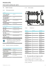
Страница 9: ...ifferenzdruckabhängig unterschritten 3 4 2 Daten für Stellantriebanschluss Gewindeanschluss M30 x 1 5 Ventilhub 1 8 mm Schließmaß 11 8 mm Schließkraft Stellantrieb 90 150 N 3 4 3 Abmessungen max 52 G1 G3 4 200 50 L SW37 52 5 max 75 32 5 Fig 6 Abmessungen Artikel Nr Kreise Länge L 1404952 2 188 mm 1404953 3 238 mm 1404954 4 288 mm 1404955 5 338 mm 1404956 6 388 mm 1404957 7 438 mm 1404958 8 488 mm ...

Страница 10: ... Heizkreisverteiler L mit der Länge des Kugelhahn L1 zusammen Die Kugelhähne 1406483 und 1406484 haben einen roten Flügelgriff Der rote Flügelgriff soll den Vorlauf kennzeichnen Die Kugelhähne 1406583 und 1406584 haben einen blauen Flügelgriff Der blaue Flügelgriff soll den Rücklauf kennzeichnen 4 2 Wärmezähler Die Installation von handelsüblichen Wärmezählern G1 und G ist möglich Die Maße des jew...

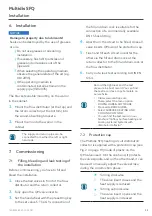
Страница 11: ...hließen Sie die Kugelhähne vor den Verteilerbalken 2 Öffnen Sie die Ventileinsätze QM vollständig 3 Stellen Sie das Handrad mit dem Voreinstellschlüssel auf den Einstellwert 5 Der G Anschluss des Füll und Entleerhahn eignet sich für den Anschluss einer handelsüblichen DN15 Schlauchverschraubung 4 Schließen Sie abgesehen von dem zu befüllenden Kreis alle Ventileinsätze QM mit Hilfe der Bauschutzkap...

Страница 12: ...n Beginnen Sie mit dem Funktionsheizen frühestens 21 Tage nach dem Verlegen von Zementestrich 7 Tage nach dem Verlegen von Calciumsulfatestrich Gehen Sie beim Funktionsheizen wie folgt vor 1 Öffnen Sie alle Ventileinsätze des Rücklaufbalkens mit Hilfe der Bauschutzkappe 2 Beginnen Sie mit einer Vorlauftemperatur zwischen 20 C bis 25 C über mindestens 3 Tage 3 Heizen Sie anschließend mit max Ausleg...

Страница 13: ... irreparabler Defekt vorliegt muss es demontiert und umweltgerecht entsorgt bzw müssen die Bestandteile wiederverwertet werden ACHTUNG Verschmutzungsgefahr für die Umwelt Nicht fachgerechte Entsorgung kann zu Umweltschäden führen Entsorgen Sie Verpackungsmaterial umweltgerecht Führen Sie Bestandteile möglichst der Wiederverwertung zu Entsorgen Sie nicht wiederverwertbare Bestandteile den lokalen V...

Страница 14: ......

Страница 15: ...mponents and surfaces 18 2 3 5 Risk of injury in case of improper work 18 2 3 6 Availability of the operating instructions 18 3 Technical description 19 3 1 Design 19 3 2 Functional description 19 3 3 Operating elements and displays 19 3 4 Technical data 21 3 4 1 Performance data 21 3 4 2 Data for actuator connection 21 3 4 3 Dimensions 21 4 Accessories and spare parts 21 4 1 Ball valve 22 4 2 Hea...

Страница 16: ...Page Multidis SFQ Contents 10 Removal and disposal 24 16 140495282 V01 09 2021 ...

Страница 17: ... 4 Declaration of conformity Oventrop GmbH Co KG hereby declares that this product has been manufactured in compliance with the essential requirements and the relevant provisions of the relevant EU directives The declaration of conformity can be obtained from the manufacturer 1 5 Symbols used Highlights important information and further additions f Action required List 1 2 Fixed order Steps 1 to X...

Страница 18: ...essurised components f Only carry out work when the system is depressurised f Observe the permissible operating pressures during operation 2 3 3 Risk of burns due to an uncontrolled discharge of hot media f Only carry out work on the heating cooling circuit when the system is depressurised f Check that the product is not leaking after work is complete f Wear safety goggles 2 3 4 Risk of burns due ...

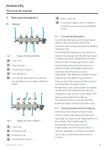
Страница 19: ...rol hydronic balancing of the surface heating and cooling systems as the valve insert is infinitely presettable diaphragm controlled and differential pressure independent The differential pressure is kept constant over the presetting and control cross section of the valve by the flow control unit integrated in the valve insert Printed stickers are included with the heating circuit distributor coll...

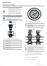
Страница 20: ...f the flow distributor return collector to shut off the supply and return pipe 1 2 3 4 5 Fig 3 Design of the QM valve insert 1 Presetting key 2 Protection cap 3 Handwheel 4 Return collector 5 Connection nipple 1 2 Fig 4 Setting of the QM valve insert 1 Set value l min 2 Indicator mark 1 2 Fig 5 Setting of the flow indicator 1 Position open 2 Position closed The flow indicator is operated using the...

Страница 21: ...n the differential pressure 3 4 2 Data for actuator connection Connection thread M30 x 1 5 Valve stroke 1 8 mm Closing dimension 11 8 mm Closing force actuator 90 150 N 3 4 3 Dimensions max 52 G1 G3 4 200 50 L SW37 52 5 max 75 32 5 Fig 6 Dimensions Item no Circuits Length L 1404952 2 188 mm 1404953 3 238 mm 1404954 4 288 mm 1404955 5 338 mm 1404956 6 388 mm 1404957 7 438 mm 1404958 8 488 mm 140495...

Страница 22: ...ng circuit distributor collector L to the length of the ball valve L1 The ball valves item no 1406483 and 1406484 have a red T handle which shall mark the supply pipe The ball valves item no 1406583 and 1406584 have a blue T handle which shall mark the return pipe 4 2 Heat meter The installation of commercially available G 1 and G heat meters is possible The dimensions of the heat meter can be obt...

Страница 23: ...f the fill and drain cock is suitable for the connection of a commercially available DN 15 hose fitting 4 Apart from the circuit to be filled close all valve inserts QM using the protection cap 5 Flush and fill each circuit one after the other via the fill and drain cock at the return collector to the fill and drain cock at the flow distributor 6 Carry out a leak test according to DIN EN 1264 Reco...

Страница 24: ...the flow temperature via the heat generator control Record incremental heating in a test record You can find the test record as a copy template on our website Visit www oventrop com There select the menu option DOWNLOADS SOFTWARE Proceed to BROCHURES Select SURFACE HEATING AND COOLING COFLOOR You can find the test record in our brochure Cofloor Surface heating and cooling systems Systems with dist...

Страница 25: ......

Страница 26: ......

Страница 27: ... 2 3 5 Risque de blessure lié à des travaux non conformes 31 2 3 6 Disponibilité de la notice d utilisation 31 3 Description technique 31 3 1 Construction 31 3 2 Description du fonctionnement 32 3 3 Dispositifs de commande et affichages 32 3 4 Données techniques 33 3 4 1 Caractéristiques 33 3 4 2 Données pour le raccordement du moteur 33 3 4 3 Encombrements 34 4 Accessoires et pièces de rechange 3...

Страница 28: ...Page Multidis SFQ Contenu 10 Démontage et traitement de déchets 38 28 140495282 V01 09 2021 ...

Страница 29: ... de conformité Par la présente la société Oventrop GmbH Co KG déclare que ce produit a été fabriqué en conformité avec les exigences essentielles et les dispositions pertinentes des directives UE concernées La déclaration de conformité est disponible sur demande auprès du fabricant 1 5 Symboles utilisés Indique des informations importantes et des explications complémentaires f Appel à l action Énu...

Страница 30: ... ce produit ne doivent être effectuées que par des professionnels dûment qualifiés De par leur formation et leur expérience professionnelles ainsi que leur connaissance des dispositions légales en vigueur les professionnels qualifiés sont en mesure d effectuer les travaux sur le produit décrit de manière professionnelle Exploitant L exploitant doit être formé à l utilisation par un professionnel q...

Страница 31: ...angé et propre pour éviter des sources d accident 2 3 6 Disponibilité de la notice d utilisation Toute personne qui travaille avec ce produit doit avoir lu et appliqué cette notice et toutes les autres notices applicables La notice doit être disponible sur le lieu d utilisation du produit Remettre à l exploitant cette notice et toutes les notices applicables 3 Description technique 3 1 Constructio...

Страница 32: ... au distributeur collecteur pour circuits de chauffage Les circuits de chauffage rafraîchissement peuvent être remplis rincés et purgés via les robinets de vidange et de remplissage 3 3 Dispositifs de commande et affichages Régler le débit à l aide de la clé de préréglage directement sur la poignée manuelle du mécanisme QM les valeurs de réglage peuvent être lues directement de l extérieur Cela pe...

Страница 33: ...e Température de service max 60 C Température de service min 2 C Pression de service Pression de service max 6 bar 600 kPa Plage de réglage 0 5 5 l min Plage de réglage Δp max 150 kPa 1 5 bar Δp min 0 5 2 l min 10 kPa 0 10 bar Δp min 2 2 8 l min 15 kPa 0 15 bar Δp min 2 8 5 l min 20 kPa 0 20 bar En dessous de Δp min un fonctionnement normal du robinet thermostatique est donné c est à dire que le d...

Страница 34: ...pièces de rechange Le produit est fourni avec de nombreux accessoires voir section 1 2 en page 29 Les robinets à tournant sphérique et les compteurs de calorie ne sont pas inclus dans la livraison Vous pouvez acheter les pièces de rechange et accessoires chez les grossistes Lors du choix du coffret veuillez noter que la profondeur et la longueur totales du distributeur collecteur pour circuits de ...

Страница 35: ...ne manette rouge pour marquer l aller Les robinets à tournant sphérique réf 1406583 et 1406584 ont une manette bleue pour marquer le retour 4 2 Compteur de calories Des compteurs de calories G 1 et G du commerce peuvent être montés Les encombrements du compteur de calories figurent dans la notice d utilisation correspondante 5 Transport et stockage Transporter le produit dans son emballage d origi...

Страница 36: ... la position 5 à l aide de la clé de préréglage Le raccordement G du robinet de vidange et de remplissage convient au raccord porte caoutchouc DN 15 du commerce 4 Fermer tous les mécanismes QM sauf le mécanisme du circuit à remplir à l aide des capuchons de fermeture 5 Rincer et remplir chaque circuit individuel l un après l autre à travers le robinet de vidange et de remplissage au collecteur pou...

Страница 37: ...ours après la pose de la chape de sulfate de calcium Procéder comme suit 1 Ouvrir tous les mécanismes du collecteur pour le retour à l aide du capuchon de protection 2 Chauffer au moins 3 jours à une température de départ entre 20 C et 25 C 3 Chauffer au moins 4 jours à la température de départ de consigne maximale Régler la température de départ via la commande du générateur de chaleur Consigner ...

Страница 38: ...é et éliminé dans le respect de l environnement ou ses composants doivent être recyclés ATTENTION Risque de pollution Une élimination non conforme peut entraîner des dommages environnementaux Éliminer l emballage dans le respect de l environnement Si possible amener les composants au recyclage Éliminer les composants non recyclables selon les réglementations locales 38 140495282 V01 09 2021 ...

Страница 39: ...Multidis SFQ 39 140495282 V01 09 2021 ...

Страница 40: ...140495282 V01 09 2021 Oventrop GmbH Co KG Paul Oventrop Str 1 59939 Olsberg Tel 49 2962 820 Fax 49 2962 82400 mail oventrop com www oventrop com ...

Отзывы: